


Heat & Glo • Escape-42DV • 2052-900 Rev. R • 10/0814
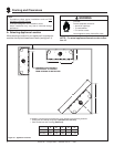
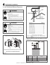
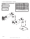
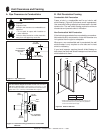
Note: Must have a 24 inches
minimum vertical vent before
attaching any elbow to the unit.
V
1
H
1
Figure 5.3
Figure 5.4
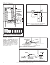
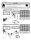
D. Vent Diagrams
1. Top Vent - Horizontal Termination
One Elbow
Two Elbows
H
2
H
1
V
1
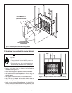
INSTALLED
HORIZONTALLY
Fire Risk. Explosion Risk.
Do NOT pack insulation or other combustibles between ceiling fi restops.
• ALWAYS maintain specifi ed clearances around venting and fi restop systems.
• Install wall shield and ceiling fi restops as specifi ed.
Failure to keep insulation or other material away from vent pipe may cause fi re.
WARNING
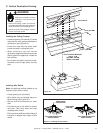
V
1
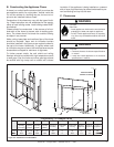
Minimum H
1
Maximum
2 ft 610 mm 7 in* 178 mm
3 ft 914 mm 2 ft 610 mm
4 ft 1.2 m 4 ft 1.2 m
5 ft 1.5 m 9 ft 2.7 m
6 ft 1.8 m 12 ft 3.7 m
7 ft 2.1 m 14 ft 4.3 m
10 ft 3.0 m 20 ft 6.1 m
20 ft 6.1 m 40 ft 12.2 m
After V
1
= 6 ft then H
1
= 2 x V ft Maximum
V
1
+ H
1
= 60 ft Maximum
*when used with approved termination caps
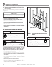
V
1
Minimum
H
1
+ H
2
3 ft 914 mm 18 in 457 mm
4 ft 1.2 m 3 ft 914 mm
5 ft 1.5 m 7 ft 2.1 m
6 ft 1.8 m 10 ft 3.0 m
7 ft 2.1 m 12 ft 3.7 m
10 ft 3.0 m 18 ft 5.5 m
20 ft 6.1 m 20 ft 6.1 m
After V
1
= 6 ft then H
1
= 2 x V
1
ft Maximum
V
1
+ H
1
+ H
2
= 60 ft Maximum
H
1
+ H
2
= 20 ft Maximum
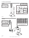
Note: Must have a 24 inches
minimum vertical vent before
attaching any elbow to the unit.
NOTE: A fl ue restrictor can
only be used in vent runs that
include no elbows and exceed
30 ft. total of straight vertical.
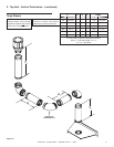
NOTE: A fl ue restrictor can
only be used in vent runs that
include no elbows and exceed
30 ft. total of straight vertical.