


Heat & Glo • CFX-CRESCENT • 705-900 Rev. P • 12/07
13
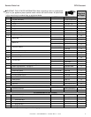
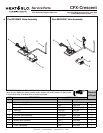
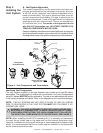
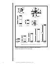
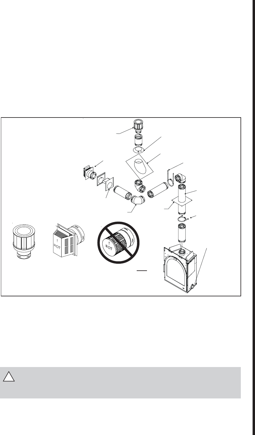
Figure 4. Vent Components and Terminations
Vent System
Termination Kits
Vent System Components
A. Vent System Approvals
This model is approved to use SL-series direct vent pipe com-
ponents and terminations (as indicated in this guide), and mod-
el AK-CFX air kits. Approved vent system components are la-
beled for identification. This pipe is tested and listed as an ap-
proved component of the fireplace. The pipe is tested to be run
inside an enclosed wall. There is NO requirement for inspection
openings at each joint within the wall. There is no required pitch
for horizontal vent runs. This model is not approved for use
with SLK-01D termination cap. NO OTHER VENTING SYS-
TEMS OR COMPONENTS MAY BE USED.
Detailed
installation instructions are included with each vent termina-
tion kit and should be used in conjunction with this Installers Guide.
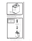
Drawing below shows vent system components and terminations.
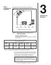
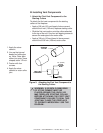
Step 3
Installing the
Vent System
!
SLK-991DA
SLK-01TRD
HORIZONTAL
TERMINATION
WALL FIRESTOP
90 DEGREE
ELBOW
VERTICAL
TERMINATION
STORM COLLAR
ROOF FLASHING
HORIZONTAL PIPE
SUPPORT
PIPE LENGTH
WALL BRACKET
CEILING
FIRESTOP
COMBUSTION
AIR DUCT COLLAR
NOTE: SLK-01D is NOT
approved for use.
NOTE: When installing the AK-CFX outside air kit, it is normally not necessary
to install the air intake cap on the same wall as the exhaust termination cap.
However, installations involving tall buildings or areas subjected to frequent high
winds, it is recommended that the air intake cap be installed on the same wall
as the exhaust termination cap.
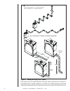
Identifying Vent Components
The vent systems installed on this gas fireplace may include up to eight 90°
elbow
assemblies. The relationships of vertical rise to horizontal run in vent configurations
using 90° elbows MUST BE strictly adhered to. The rise to run relationships are shown
in the venting drawings and tables. Refer to the diagrams on the next several pages.
NOTE: TWO 45° ELBOWS MAY BE USED IN PLACE OF ONE 90° ELBOW.
RISE TO RUN RATIOS IN THE VENT SYSTEM MUST BE FOLLOWED IF 45°
ELBOWS ARE USED.
WARNING: THIS UNIT IS DESIGNED TO OPERATE USING OUTSIDE COM-
BUSTION AIR. IT IS MANDATORY TO INSTALL AN AK-CFX AIR KIT USING
4-INCH INSULATED DUCTING. THE 4-INCH (102MM) DUCT COLLAR FOR
THE AIR KIT WILL COME MOUNTED TO THE FIREPLACE. SEE FIGURE 6.