


Hearth & Home Technologies • BE-36-C, BE-36-CIPI • 397-981 Rev. R • 2/05
31
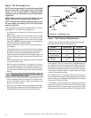
Step 8. Wiring the Fireplace
NOTE: Electrical wiring must be installed by a licensed
electrician.
CAUTION: DISCONNECT REMOTE CONTROLS IF AB-
SENT FOR EXTENDED TIME PERIODS. THIS WILL PRE-
VENT ACCIDENTAL FIREPLACE OPERATION.
For Standing Pilot Ignition Wiring
Appliance Requirements
• This appliance DOES NOT require 110-120 VAC to operate.
WARNING: DO NOT CONNECT 110-120 VAC TO
THE GAS CONTROL VALVE OR WALL SWITCH
OR THE APPLIANCE WILL MALFUNCTION
AND THE VALVE WILL BE DESTROYED.
Optional Accessories
Optional fan and remote control kits require that 110-120
VAC be wired to the factory installed junction box before
the fireplace is permanently installed.
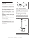
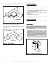
Wall Switch
Position the wall switch in the desired position on a wall.
Run a maximum of 25 feet (7.8 m) or less length of 18
A.W.G. minimum wire and connect it to the fireplace ON/
OFF switch pigtails.
!
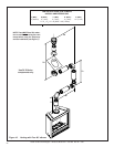
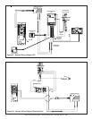
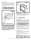
Figure 31.
Standing Pilot
Ignition Wiring Diagram
!
!
Wall Switch (Required)
A wall switch must be installed for this fireplace. This will
allow the unit to operate with 110-120 VAC power or battery
operation.
Position the wall switch in the desired position on a wall.
Run a maximum of 25 feet (7.8 m) or less length of 18
A.W.G. minimum wire and connect it to the fireplace ON/
OFF switch pigtails.
WARNING: DO NOT CONNECT 110-120 VAC
TO THE WALL SWITCH OR THE CONTROL
VALVE WILL BE DESTROYED.
Optional Accessories
Optional remote control kits require that 110-120 VAC be
wired to the factory installed junction box before the fire-
place is permanently installed.
CAUTION: LABEL ALL WIRES PRIOR TO DISCONNEC-
TION WHEN SERVICING CONTROLS. WIRING ERRORS
CAN CAUSE IMPROPER AND DANGEROUS OPERA-
TION. VERIFY PROPER OPERATION AFTER SERVICING.
Operation using Battery Power
This fireplace has an optional battery operation. The sys-
tem is fully functional with the use of two “D” size batteries
without ordinary 110-120 VAC power.
Wiring to the battery pack should be left disconnected in
order to conserve battery life. In the case of a loss of power,
simply connect red and black wire leads to activate battery
power (connect red to red, black to black). The fireplace
can be used as necessary. Once power (110 VAC) is re-
stored, disconnect red and black wire leads to extend bat-
tery life.
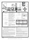
Intermittent Pilot Ignition (IPI) Wiring
Appliance Requirements
This appliance requires that 110-120 VAC be wired to the
factory installed junction box. Maintain correct polarity when
wiring the junction box.
WARNING: DO NOT CONNECT 110-120 VAC
TO THE GAS CONTROL VALVE OR THE AP-
PLIANCE WILL MALFUNCTION AND THE
VALVE WILL BE DESTROYED.
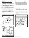
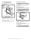
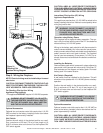
Installing the Batteries
Remove battery pack which is secured in place adjacent to
gas control valve (secured with velcro strip). Orient two “D”
size batteries per the diagram on battery pack. Re-install
battery pack in the same location.
CAUTION: LABEL ALL WIRES PRIOR TO DISCONNEC-
TION WHEN SERVICING CONTROLS. WIRING ERRORS
CAN CAUSE IMPROPER AND DANGEROUS OPERATION.
VERIFY PROPER OPERATION AFTER SERVICING.
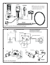
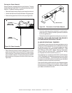
THERMOSTAT
WIRE ASSEMBLY
VALVE
RED
WHITE
PIEZO
PILOT
THERMOCOUPLE