


Hearth & Home Technologies • BE-36-C, BE-36-CIPI • 397-981 Rev. R • 2/05
15
Step 3. Installing the Vent System
A. Vent System Approvals
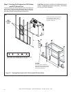
This model has vent starting collars on both the top and the
back of the unit. Depending upon the installation, decide
which ONE set of starting collars will be used to attach the
vent system. The starting collar sealing cap must remain
on the starting collar NOT used.
This model uses SL-D-series, direct vent components when
using the TOP vent collars. This pipe is tested and listed
as an approved component of the fireplace. The pipe is
tested to be run inside an enclosed wall. There is no
requirement for inspection openings at each joint within the
wall. There is no required pitch for horizontal vent runs when
using DVP-Series and SL D-Series pipe.
This model also uses DVP-series direct vent components
when using the REAR vent collars.
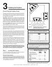
The flame and ember appearance may vary based on the
type of fuel burned and the venting configuration used.
WARNING: YOU MUST NOT MIX DVP-SERIES
AND SL D-SERIES COMPONENTS IN ANY VENT
SYSTEM CONFIGURATION.
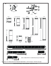
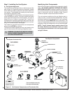
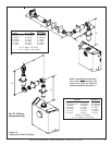
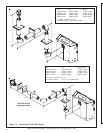
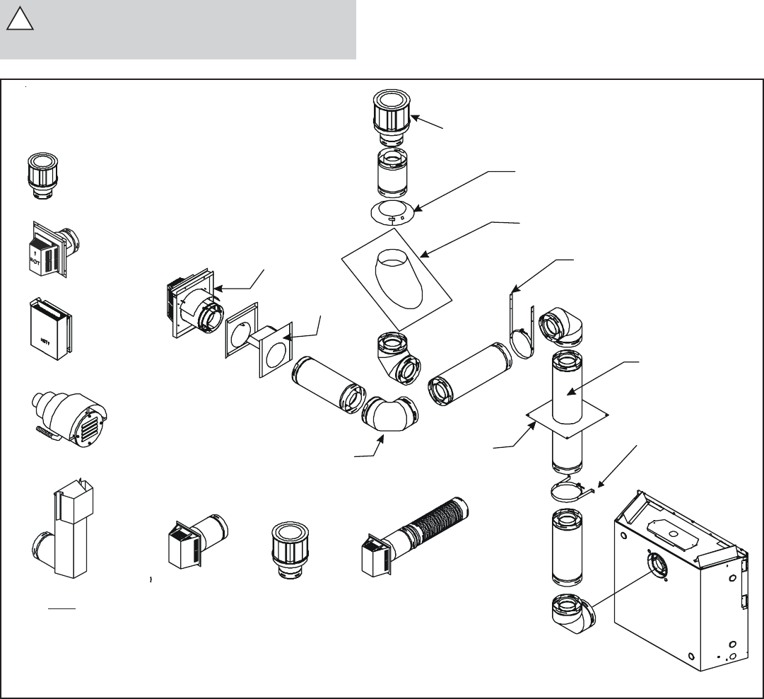
Identifying Vent Components
Approved vent system components are labeled for identifi-
cation. NO OTHER VENTING SYSTEMS OR COMPO-
NENTS MAY BE USED. Detailed installation instructions
are included with each vent termination kit and should be
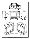
used in conjunction with this Installers Guide. Figure 5
shows vent system components and terminations.
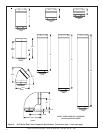
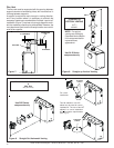
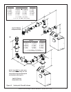
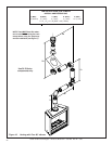
The vent systems installed on this gas fireplace may in-
clude one, two, or three 90°
elbow assemblies. The rela-
tionships of vertical rise to horizontal run in vent configura-
tions using 90° elbows MUST BE strictly adhered to. The
rise to run relationships are shown in the venting drawings
and tables. Refer to the diagrams on the next several pages.
NOTE: Two 45° elbows may be used in place of one
90° elbow. Maximum and minimum rise to run ratios
must always be maintained in the vent system when
using 45° elbows.
!
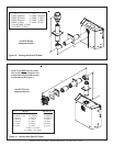
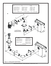
Figure 6. Vent System Components and Termination Kits
Vent System Termination Kits
Vent System Components
* For use with flex vent only.
** For use on IPI units only.
HORIZONTAL
TERMINATION
WALL
FIRESTOP
90 DEGREE
ELBOW
VERTICAL
TERMINATION
STORM COLLAR
ROOF FLASHING
HORIZONTAL PIPE
SUPPORT
PIPE LENGTH
WALL BRACKET
CEILING
FIRESTOP
SLK-991DA
SLK-01TRD
SLK-01TRF
DVP-TVHW
SL D-SERIES
DVP-SERIES
SL-FLEX2-01TRF
(SL-Series)
(SL-Series)
DVP-TRAP
DVP-TB1
DVP-TV
PVK-80
SLK-SNKD
*
**
(Required
to have a
minimum of 3
feet of vertical
in the vent
system)
(There
MUST be a 25%
reduction in total H
when using the snorkel
cap except when using
the simple up and out
installation (see Fig. 7)
(For use with both DVP
and SL-D venting)
Î