


HearthStone Quality Home Heating Products Inc CHAMPLAIN Gas-Fired Direct Vent
33
touched. Use only metal tools for this
adjustment.
Moving the nut toward the front of the stove
increases the air and moving the nut toward
the back of the stove decreases the air.
Tighten the nut after making adjustment.
The air shutter is factory set and only a
qualified gas technician should make
adjustments.
Note: Very little movement is needed to
substantially change the burn and flame
patterns.
Some conditions cannot be corrected
through air shutter adjustment; an
adjustment must be made to the gas supply
pressure. Supply line/manifold gas line
pressure adjustments must be performed by
qualified service personnel. Do not attempt
to complete any part of the installation or
adjustment of this unit unless technically
qualified to do so.
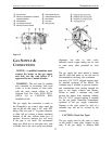
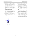
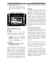
PILOT ADJUSTMENT
The pilot light is preset by the manufacturer
and should not need adjustment. The pilot
light flame should be large enough to engulf
the thermopile and thermocouple located
next to the pilot, but not so large as to create
excessive noise or consume excessive gas.
(Refer to figure 18) However, it can be
adjusted by means of the pilot light
adjustment screw located on the gas control
valve. Open the valve door to access the
pilot adjustment screw. Note that the pilot
flame must engulf the thermopile so that the
thermopile can generate sufficient
milli-voltage (325 to 500-mv) to power the
milli-volt gas control valve. The flame on
the pilot should look like Figure 18.
Controlling the Champlain by the wall-
mounted thermostat may become erratic,
nonexistent, or the unit may go out, if the
pilot flame is too small or misdirected away
from the thermopile.
Figure 18 Pilot Adjustment
WARNING
The control has an interlock device. If the
stove has been lit, it will not relight
immediately. After shutting off all gas flow,
the pilot burner cannot be relit until the
thermocouple has cooled, allowing the
electromagnet to be released (Approx. 60
sec.). The gas control knob is designed to
be operated by hand. Do not use any tools
during this operation.
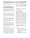
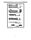
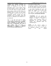
BURNER FLAME APPEARANCE
Once the unit is lit, observe the flame
pattern and adjust as necessary. Also, a
periodic visual check of the burner flame
should be performed. The burner flames can
be adjusted by means of the air shutter. To
determine if the burner flame needs
adjustment, it is necessary to view the flame
pattern with the variable output control knob
at its highest setting (turn fully clockwise).
Allow the unit to operate for 10 minutes
enabling the entire unit to reach temperature
and for the flame pattern to stabilize. The
flame pattern should be similar to the one
shown in Figure 19. There are several
guidelines to aid in determining if the flame
pattern is correct:
1. The flame should not be dirty, smoky,
sooty, or lick the top of the stove.