


1. PLUG IN STOVE, NO RESPONSE
A. Check the power supply for 120 volts AC.
B. Check the fuse in the junction box (7 amp, 120 volt fuse
AGC-7).
C. Check snap disc #3 (unplug stove before checking). Push
reset on snap disc #3.
D. Control box (consult your dealer).
2. CALL LIGHT ON, NO FIRE, NO FUEL IN FIREPOT
A. Check the hopper for fuel, sawdust or bridging of pellets
in the bottom of the hopper. If the hopper is low on fuel,
vacuum can be lost through the hopper.
NOTE: Sometimes there might still be fuel in the
hopper. If so, continue to check the areas below.
B. Make sure that the exhaust blower is operating.
C. Check the venting system for obstructions that might
cause restrictions, which would cause the vacuum safety
switch to shut off the auger.
D. Check the heat exchanger system for high ash content. If
buildup is present, clean the heat exchanger system.
E. Push the reset button, and try, to light the stove again.
3. CALL LIGHT ON, NO FIRE, PARTIALLY-BURNED
FUEL IN THE FIREPOT
A. Clean the firepot. Check that the igniter hole is clean and
the cleanout plate is tightly in place.
B. Inspect the thermocouple and cover for the following:
1. The cover needs to be making contact with the end of
the thermocouple.
2. The thermocouple and the cover should extend
approximately 1” (25mm) into the firepot (for
accurate temperature reading).
3. Push the restart button. When the thermocouple
reaches 200°F (93°C) the GREEN LIGHT will come
on, and at 1000°F (538°C) the RED LIGHT will
come on.
NOTE: If the lights fail to come on after the fire
starts, the thermocouple may be faulty.
C. If the thermocouple appears good, the control box may be
the problem (consult your dealer).
4. CALL LIGHT ON, NO FIRE, UNBURNED PELLETS IN
FIREPOT
A. Clean the firepot.
B. Push the reset button.
C. Check the igniter to see that it comes on. If it does not turn
on, check the following:
1. Check the connections under the firepot. (Ceramic wire
nuts must be used to withstand the heat produced by
the firepot.)
2. Make sure that the igniter is property installed in the
igniter bracket. It should fit tightly, and be centered in
the igniter hole.
5. SLOW OR SMOKY START-UP
A. Clean the firepot. Check the firepot gasket for a good
seal between the firepot and the firebox floor.
B. Check the combustion blower (make sure that it is
starting when the thermostat calls for heat).
C. Visually check the cleanliness of the firebox, the heat
exchangers and the venting system.
D. The feed rate may be too high. If necessary, adjust with
the fuel adjustment rod located in the hopper.
E. Due to elevation, the air adjusting plate (located on the
left side in the cleanout area of the pedestal) may need to
be adjusted to get the right air to fuel ratio.
6. STOVE RUNS FOR 10 MINUTES, THEN STOPS
FEEDING FUEL
A. Inspect the thermocouple and the cover.
1. The cover needs to make contact with the end of the
thermocouple.
2. The thermocouple and the cover should extend
approximately 1 n (25mm) into the firepot.
3. Push the reset button. The thermocouple test lights
located on the control box will automatically turn on;
when the thermocouple reaches 200°F (93°C) the
GREEN LIGHT comes on, and at 1000°F (538°C)
the RED LIGHT comes on. If they fail to turn on
after the fire starts, the thermocouple may need
replacement.
4. Check the control box (consult dealer).
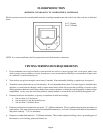
7. FEED SYSTEM FAILS TO START
A. Make sure that the front door to the firebox and the door to
the ash cleanout in the pedestal are closed tightly.
B. Check to make sure that the exhaust blower is coming on
and working.
C. Check the heat exchangers and the venting system for
obstructions or heavy ash buildup.
D. The vacuum switch hose may be plugged.
1. Pull the hose off and blow through it to make sure it is
clear.
NOTE: Unplug stove from power outlet first.
E. Downdrafts or poor venting systems that do not follow
manufacturers recommendations can also cause this
problem.
F. Check the hopper and the feed system for blockage.
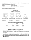
TROUBLESHOOTING
CAUTION: UNPLUG STOVE BEFORE SERVICING
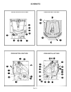
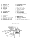
NOTE: In order to identify the component location, refer to schematics on pages 13 and 14.
Page 18