


1. POWER SUPPLY
A. Check the wall receptacle for 120 volt, 60 Hz (standard
current). Make sure the outlet is grounded and has
the correct polarity.
2. FUSE
A. The fuse is located on the left side, next to the restart
button and the indicator light. However, to access
the fuse, you must remove the left side panel. To
inspect the fuse, push the fuse holder in and turn the
holder cap counterclockwise, then pull out. Replace
with a standard 7 amp 120 volt fuse, if necessary. If
the fuse continues to blow, contact your local dealer.
3. RED CALL LIGHT
A. The red call light is located on the left side next to the
reset button. The function of the red call light is to
indicate that the thermostat is calling for heat.
B. If the thermostat is calling for heat, the stove is
burning, and the light is not on, check the bulb.
Replace with a 28 volt AC (#85 lamp) bulb.
4. RESET BUTTON
A. The reset button is located on the left side of the
stove, next to the red call light. The function of the
button is to momentarily open the thermostat circuit,
which restarts the system. However, this will only
work when the thermostat is calling for heat and the
red light is on.
B. If the light is on, there is no fire, and there is fuel in
the firepot, push the reset button and wait for ignition.
You should have a fire within five minutes.
C. If the light does not go out when the reset button is
pushed, the reset button switch may be faulty.
Contact your local dealer.
5. VACUUM SWITCH
A. The vacuum switch is located on the left side of the
stove, just above the red call light and the reset button.
This switch turns the feed system on when vacuum
is present in the firebox. Check the rubber hose for
leaks or cracks if the feed system fails to start. Also,
be sure there is no restriction in the exhaust system
and the exhaust blower is running. The vacuum
switch is a safety device to shut off the feed motor
under the conditions above.
B. If the exhaust or the heat exchanger system is dirty
or plugged, the vacuum switch will keep the feed
system from starting.
C. If the firebox door is open, the vacuum switch will
keep the feed system from starting.
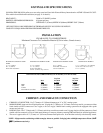
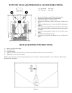
6. JUNCTION BOX AND WIRING HARNESS
A. The junction box and the wiring harness are located
on the left side of the stove. They are part of a
three piece set. The lower junction box contains
both the capacitors, the thermocouple terminal block
and the computer card receptacle for the control
box. The upper junction box contains the red call
light, the reset button, the thermostat terminal block,
the 7 amp fuse, and the power receptacle. The wiring
harness connects the upper and the lower junction
boxes and also disperses connections to the other
electrical components.
B. The junction box and the wiring harness are replaced
as one component.
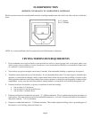
7. THERMOSTAT
A. The stove is designed to run on a 24 volt AC
thermostat. Remove the front cover and check to
see that the contact points are not stuck in either the
open or closed position, and that both wires are
property connected to the thermostat.
NOTE: The anticipator should be set on the
lowest setting available. Also, check the wire
leads at the terminal block located at the back
of the stove for loose connections.
8. CONTROL BOX
A. The control box is located on the lower left side of
the stove. It is plugged into the junction box. If the
stove has just been plugged in and the combustion
blower does not start, check the control box to see
that it is securely plugged in. If this does not solve
the problem, consult your local dealer.
B. The green light located on the front of the control
box notifies you that the stove has reached a
temperature of 200°F (93°C) in the firepot. If this
light is not lit in the first four minutes of operation,
the stove will shut down. Check the thermocouple.
C. The red light located to the left of the green light is to
indicate that the stove has reached operating
temperature. If this light does not come on in the
first nine minutes of startup, the stove will shut down.
The stove will not try to relight again by itself. You
must manually push the reset button to restart the
cycle.
D. If you suspect a problem with the control box,
disconnect the power supply from the stove, then
remove the control box and take it to your nearest
Quadra-Fire dealer for testing.
NOTE: Do not open the control box. This will
void the warranty. Do not plug in or remove
control box without first unplugging the stove.
COMPONENT INFORMATION
Page 16