


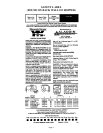
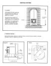
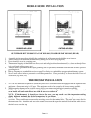

MOBILE HOME INSTALLATION
OUTSIDE AIR KIT FOR 800 NOVA: PART #811-0420 (FLOOR) OR PART #811-0430 (REAR)
1 An outside air inlet must be provided for the combustion air and be unrestricted while the stove is in use.
2. The stove must be secured to the mobile home by bolting it to the floor (using lag bolts).
3. Do not install the stove in a sleeping room.
4. The structural integrity of the mobile home floor, walls and ceiling/roof must be maintained (i.e., do not cut through floor
joists, wall studs, ceiling trusses, etc.).
5. The stove must be grounded with #8 copper grounding wire or equivalent, terminated at each end with an NEC approved
grounding device.
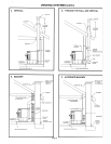
6. Refer to clearances to combustibles section on page 5 for listings to combustibles and appropriate chimney systems.
7. Seal all wall or floor inlets to prevent air or moisture penetration. Check periodically to ensure the inlet is f ree of
obstruction (e.g., snow, ice).
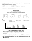
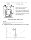
THERMOSTAT INSTALLATION
1. A 24 volt AC thermostat is required to operate this pellet stove. Some thermostats are equipped with an adjustable heat
anticipator. Our current rating is .05 amps. The anticipator needs to be adjusted to the lowest setting available.
2. When mounting a thermostat on a wall, be sure to follow your thermostat installation instructions carefully.
NOTE: Be sure the thermostat is mounted level for accurate readings. The thermostat should be mounted
on an inside wall and not in direct line with the stove convection air.
NOTE: If the thermostat is located too close to the stove, you may need to set the temperature setting
slightly higher to maintain the desired temperature in your home.
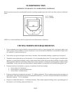
3. There is a four screw terminal block located on the back of the stove beside the fuse receptacle, adjacent to the power
cord inlet. The top and bottom screws are the mounting screws for the terminal block. The center two screws are for
the thermostat wires. Attach the red wire to the second screw from the top on the terminal block and the white wire to
the third screw from the top.
Page 11