


September 1, 2008
433-1390G
Page 35
7100FP EPA Woodburning Fireplace
R
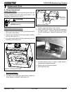
NOTE: Secure the duct so that clearance to the fire-
place outer wrap is maintained. Tape all seams with
aluminum tape 1-1/4 in. (32mm) minimum width or as
specified by local codes.)
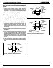
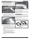
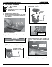
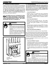
10. Seal all the way around the inside of the Return Air Grille
to prevent hot air being drawn back into the venting system
using gasketing supplied with the kit. Leave 1/4 in. (6mm)
clearance from all 4 outer edges. Trim excess gasketing.
See Figure 35.3.
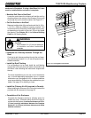
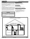
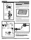
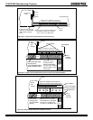
Securely Twist
Lock B-Vent to
Adapter
Secure B-Vent to Fan Housing
with sheet metal screws
Return Air Grille
Install with Louvers
pointed down
Bracket
Can rotate
180
o
2x4Wall
Fan Housing
1/2 in. (13mm)
clearance to
combustibles
must be
maintained.
2x4wall
Sheet Rock
Seal grille using gasketin
g supplied with the kit
Leave 1/4" (6mm) clearance from
all 4 outer edges
11. Install the variable speed wall rheostat (with setting on
“OFF”) in a convenient location. This switch will control the
Heat-Zone fan operation.
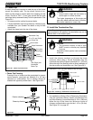
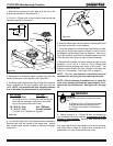
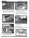
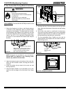
12. Remove the Junction Box. Wire 110 VAC service TO the
wall rheostat and FROM the wall rheostat to the fan Junction
Box. Use wire nuts to secure the 110 VAC service wires to
the hot (black) and neutral (white) fan wires and screw the
110 VAC ground wire to the Junction Box. See Figure 35.4.
Figure 35.1
Figure 35.2
Figure 34.3
Junction Box Removed
Wire Clamp
Wire Nuts
Junction Box
Black
White
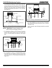
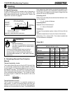
13. Secure the Return Air Grille to the fan housing making
sure it is flush. The grille must be installed with the louvers
pointing down.
NOTE: DO NOT USE ADJUSTABLE REGISTERS.
14. Complete the fireplace installations as per the instruc-
tions found in your Owner’s Manual.
Figure 35.4