


Page 34
433-1390G
September 1, 2008
R
7100FP EPA Woodburning Fireplace
INSTALLATION
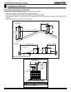
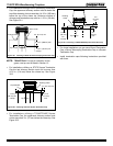
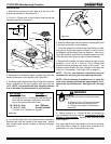
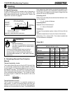
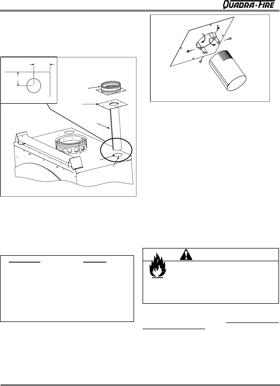
1. Remove the knockout or cover plate from the top of the
fireplace and discard it. See Figure 34.1.
2. Cut a 3 in. (76mm) hole in the insulation board as per the
dimensions shown in Figure 34.1.
Adapter
Mounting
Plate
Starter Pipe
Knockout
Cut a 3 in. (76mm) hole
in insulation board
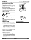
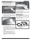
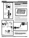
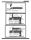
5. On the Mounting Plate, hand bend the tabs downward.
Slide the tabs over the outside of the starter pipe. Secure
with 4 sheet metal screws included in fasteners package.
Figure 34.3.
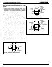
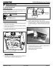
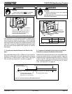
3-13/16 in.
(97mm)
3-1/8 in. (79mm)
C
L
Run Length Cut Pipe
20 - 40 ft (6-12m) 2 in. (51mm)*
*A minimum of 2 in. (51mm) pipe must be used to
cover the raw insulation to prevent it tfrom blow-
ing out through the Return Air Grille.
10 - 20 ft (3 - 6m) 8 in. (203mm)
3 - 10 ft (1 - 3m) No cut needed**
**Use full 16 in. (406mm) as supplied
3. Determine the necessary length of starter pipe from the
following table and cut as required. See Figure 34.2.
4. The starter pipe is shipped flat. After cutting to the required
length, manually roll the pipe together and snap lock into
place. NOTE: It is important the pipe length be adhered
to or it will affect the performance of your fireplace.
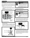
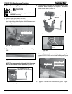
6. Slide the starter pipe into the fireplace, matching the holes
in the plate to the holes in the fireplace.
7. Place the Adapter on the Mounting Plate lining up holes.
Using the 4 sheet metal screws included in the kit, secure
the Adapter and Mounting Plate into fireplace. After secur-
ing to the fireplace, tape down the Adapter edges to the top
of the fireplace with aluminum tape to prevent leakage.
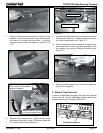
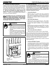
8. Determine the location for the air register and fan housing
assembly. Cut a 7-5/8 in. x 13-5/8 in. (143 x 346mm) hole
between framing members (wall studs or floor joists). The
brackets can be rotated 180° and mounted to the back side
of the 2 x 4 if necessary. See Figure 35.2 on page 35.
NOTE: The fan and electrical connections must be
accessible for servicing per local code requirements.
NOTE: If the fan housing is installed in a 2 x 4 wall, the
front of the housing will protrude approximately 1/4 in.
(6mm) from the finished wall. See Figure 35.1 on page
35.
9. Attach enough 6 in. (152mm) B-Vent as required for
your installation to the fan housing. A maximum of (4) 90°
elbows is recommended. Securely twist lock the B-Vent
to the Adapter.
Also screw the B-Vent to the outlet box on the fan housing.
See Figure 35.2 on page 35.
Support duct at intervals of no
greater than 4 ft (1 m) as required by local code.
Figure 34.1
Figure 34.2
Figure 34.3
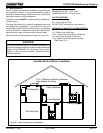
Fire Risk
Comply with all minimum clearances speci-
fied.
• A minimum 1/2 in. (13mm) air clearance
must be maintained at the back and 1
in. (25mm) to the sides of the fireplace
assembly.
WARNING