


Page 28
433-1390G
September 1, 2008
R
7100FP EPA Woodburning Fireplace
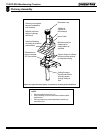
NAIL
FLASHING
PLATE
CHIMNEY
THIMBLE
EXTENSION
SCREW
FLASHING
THIMBLE
A
DJUSTABLE
EXTENSION
HOLES
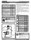
FLASHING
CHIMNEY
FLASHING
PLATE
NAIL
THIMBLE
SCREW
THIMBLE
EXTENSION
B.
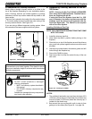
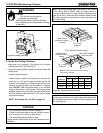
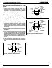
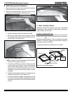
SL-300 Series Ceiling/Roof Thimble
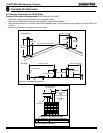
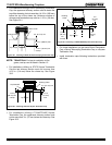
1. Locate the point where the chimney will exit the roof by
plumbing down to the center of the chimney. Lay out, cut
and frame a 14-1/2 in. (368 mm) square opening (measured
on the horizontal) through the ceiling and roof structure.
Consult local codes for framing details.
2. The thimble must extend completely through the roof struc-
ture shielding combustible materials. Five location holes
have been provided to allow for a variety of ceiling/roof
thicknesses. A Thimble Extension is required when the
ceiling/roof thickness exceeds 12-1/2 in. (318 mm). The
extension should overlap the thimble one inch.
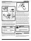
3. To attach the extension to the thimble, drill 1/8 in. (3 mm)
holes through the outer shield of the thimble using the
predrilled holes in the extension as guides. Attach the
extension to the thimble using the screws provided with
the extension.
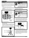
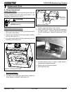
4. Install the thimble assembly and nail it securely to the fram-
ing members.
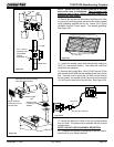
5. Center the flashing over the chimney and nail it to the roof
using the Stormguard nails provided. Keep gaps between
the flashing plate and the roof to a minimum. Caulk the flash-
ing plate and roof junction as well as the vertical seam on
the flashing. All nail heads must be caulked with a roofing
sealant.
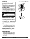
6. Finish assembling the chimney storm collar and termina-
tion cap following the installation instructions provided with
them.
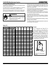
CHIMNEY
FLASHING
PLATE
JOISTS
NAIL
THIMBLE
FLASHING
Figure 28.1 Installing Part: 12966A, Configuration 1
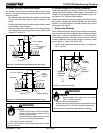
Figure 28.2 Installing Part 12966A, Configuration 2
Figure 28.3 Installing Part 12966A Configuration 3
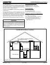
NOTE: REQUIRED for manufactured homes with vaulted
ceilings.