


September 1, 2008
433-1390G
Page 23
7100FP EPA Woodburning Fireplace
R
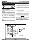
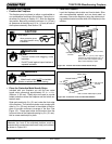
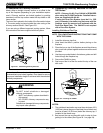
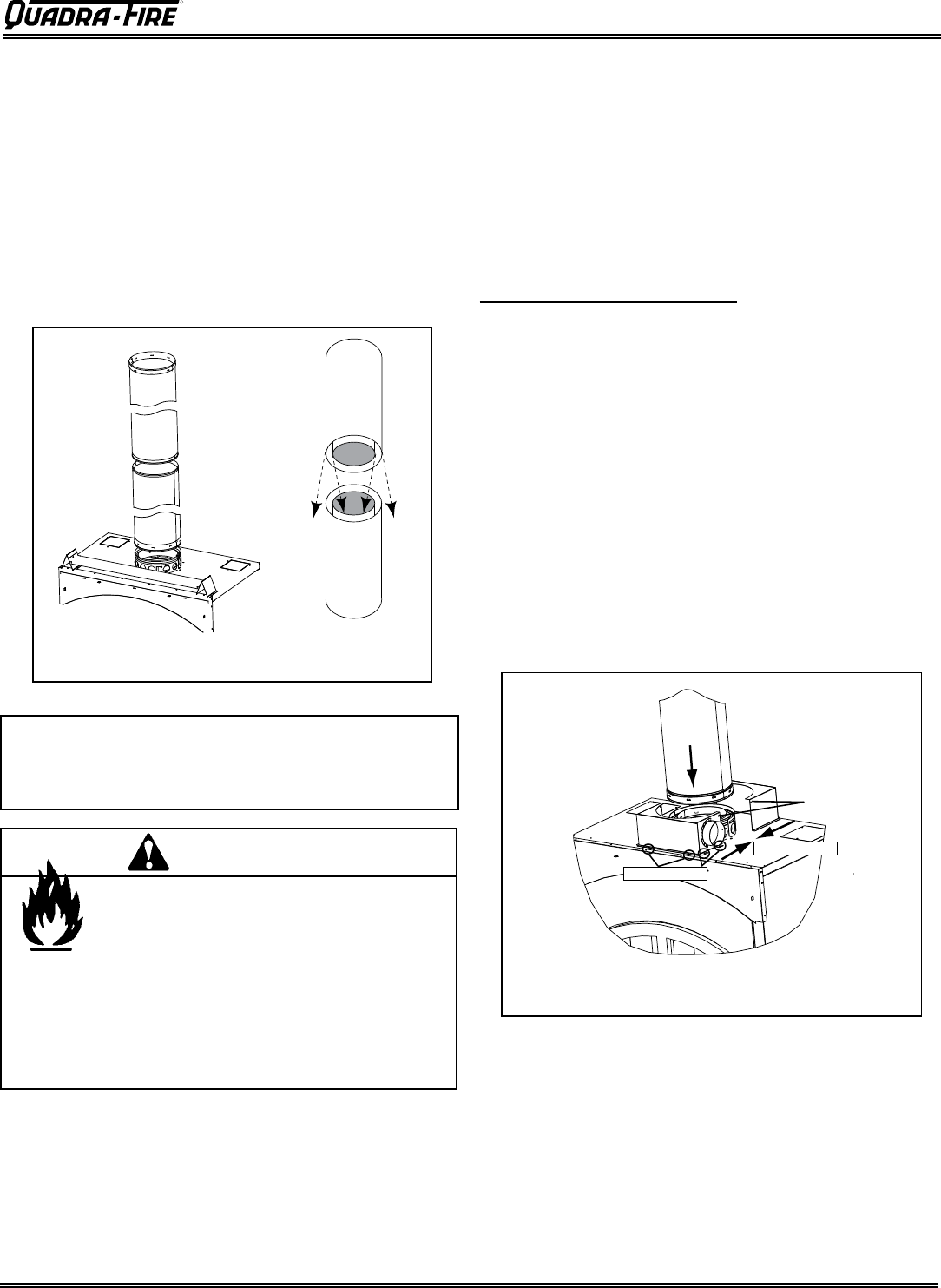
D. Assemble the Chimney Sections
Attach either a straight chimney section or an offset to the
top of the fireplace (depending on your installation require-
ment). Chimney sections are locked together by pushing
downward until the top section meets the stop bead on the
lower section.
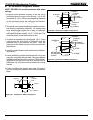
The inner flue is placed to the inside of the flue section below
it. The outer casing is placed outside the outer casing of the
chimney section below it. See Figure 23.1.
If you are using a different approved venting system, follow
the instructions that were supplied with that system.
Note: Inner flue and outer liner sections cannot be
disassembled once locked together. Plan ahead to ensure
the proper installation height is achieved with the selected
chimney components.
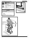
Figure 23.1 Assembling Chimney Sections
Fire Risk
Do NOT install substitute or damaged
chimney components.
• MUST use chimney system described in
this manual.
• NO OTHER chimney components may
be used.
Substitute or damaged chimney components
may impair safe operation.
WARNING
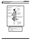
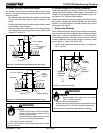
E. Assembling Chimney Sections for the SL-
300 Series
NOTE: Chimney Air Kit, Part CAK4A is REQUIRED
when using the SL-300 Pipe Series. Detailed instruc-
tions are supplied with the kit.
If using the Dura-Plus System (must be 8 in. (203
mm) in diameter), the starter ring that came with the
fireplace must be removed and replaced with the
Dura-Plus Base Plate. The CAK4A is not required
with a Dura-Plus System.
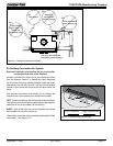
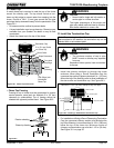
Attach
Flue First
CAK4A
Secure with Screws
Provided
Push Together
Secure to Top
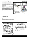
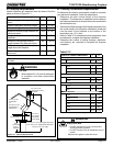
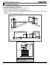
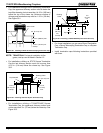
Installing CAK4A and Flex Pipe
NOTE: FOLLOW DETAILED INSTRUCTIONS THAT COME
WITH THE CAK4A.
1. Install the chimney pipe first.
2. Hand bend the tabs in position before placing on the
fireplace.
3. Place the box on top of the fireplace around the chimney
pipe, push both pieces together and secure with screws
provided.
4. Use the pre-punched holes in the tabs as guides and drill
holes through the fireplace top.
5. Secure the CAK4A in place.
6. Seal around the kit at the flue and at the top of the can
with caulk.
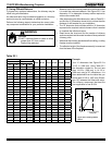
NOTES:
1.
The outside air termination cap must be a minimum of 6 ft
(1829 mm) above the ground and kept free of debris and
must be at least 3 ft (914 mm) below the chimney top, if
installed in the chase zone.
2. Seal around the cap and flex with caulk to stop air from
getting in to the chase (See Figure 24.1 on page 24).
Figure 23.2 Installing the CAK4A