


9
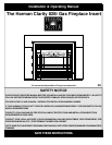
The Clarity Fireplace Insert, when installed, must
be electrically grounded in accordance with local
codes or, in the absence of local codes, with the the
current edition of the National Electrical Code,
ANSI/NFPA 70 in the United States or the current
Canadian Electrical Code CSA 22.1 in Canada.
This appliance is equipped with a three-prong
(grounding) plug for protection against shock haz-
ard and should be plugged directly into a properly
grounded three-prong receptacle. Do not cut or re-
move the grounding prong from the plug.
NOTE: The convection fan requires a 120 VAC
supply for operation, but the heater can be operated
without the fan as in the case of a power outage.
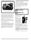
Plug the 3-prong grounded electrical cord plug
into the wall outlet.
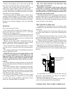
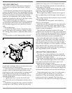
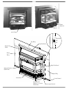
CONNECTING THE
OPTIONAL THERMOSTAT
If the optional thermostat is used, it must be
plugged into the terminal strip located behind the
right side air inlet grill. It can be accessed by first
opening the control access door and then pulling up
and forward on the air grill. The terminal block will
then be visible.
When installing a millivolt control system, use
only a special low resistance thermostat. Do not use
a regular heating thermostat.
Be sure that all electrical connections are clean,
free from corrosion, and tight. Inspect connections
periodically to confirm that no corrosion has built
up over time.
When properly installed and maintained, a mil-
livolt control system should give many years of
trouble-free service.
It is important to use wire of a gauge proper for
the length of the wire:
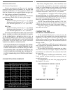
RECOMMENDED WIRE GAUGES
Maximum Wire
Length Gauge
100' 14
60' 16
40' 18
25' 20
15' 22
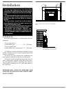
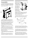
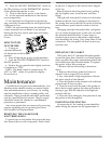
INSTALLING THE INSERT
BEFORE OPERATING
Gas Pressure Requirements
Correct gas pressure and the use of a properly
sized gas supply line are essential for the safe and
efficient performance of this appliance. Make sure
that the plumber or gas supplier checks the gas sup-
ply line and gas pressure at installation.
NOTE: Improper gas pressure can affect heater
performance, flame color, or cause pilot outage.
Natural Gas:
Maximum inlet pressure 7.0" w.c. (1.74 kPa)
Minimum inlet pressure 5.0" w.c. (1.25 kPa)
Gas manifold pressure 3.5" w.c. (0.87 kPa)
LPG Gas:
Maximum inlet pressure 13" w.c. (3.24 kPa)
Minimum inlet pressure 11" w.c. (2.74 kPa)
Gas manifold pressure 10" w.c. (2.49 kPa)
DO NOT USE THIS HEATER IF ANY PART HAS
BEEN UNDER WATER OR EXPOSED TO MOIS-
TURE CORROSION. IMMEDIATELY CALL A
QUALlFlED SERVICE TECHNICIAN TO INSPECT
THE HEATER AND REPLACE ANY PART OF THE
CONTROL SYSTEM AND ANY GAS CONTROL
WHICH HAS BEEN UNDER WATER.
NE PAS SE SERVIR DE CET APPAREIL S'IL A ÉTRE
PLONGÉ DANS L'EAU, COMPLÉTEMENT OU EN
PARTIE. APPELER UN TECHNICIEN QUALIFIÉ
POUR INSPECTER L'APPAREIL ET REMPLACER
TOUTE PARTIE DU SYSTÈME DE CONTRÔLE ET
TOUTE COMMANDE QUI ONT ÉTÉ PLONGÉS DANS
L'LAU.
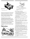
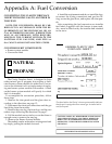
CONNECTING THE CORDSET
Pipe Length Schedule 40 Pipe Tubing, Type L
(Feet) Inside Diameter Outside Diameter
N.G. L.P. N.G. L.P.
0-10 1/2" 3/8" 1/2" 3/8"
1.3 cm 1.0 cm 1.3 cm 1.0 cm
10-40 1/2" 1/2" 5/8" 1/2"
1.3 cm 1.3 cm 1.6 cm 1.3 cm
40-100 1/2" 1/2" 3/4" 1/2"
1.3 cm 1.3 cm 1.6 cm 1.3 cm
100-150 3/4" 1/2" 7/8" 3/4"
2.0 cm 1.3 cm 2.3 cm 2.0 cm
RECOMMENDED GAS PIPE DIAMETER
NOTE: NEVER USE PLASTIC PIPE. CHECK TO
CONFIRM WHETHER YOUR LOCAL CODES ALLOW
COPPER TUBING OR GALVANIZED PIPE.
Evaluation notes were added to the output document. To get rid of these notes, please order your copy of ePrint IV now.