


10
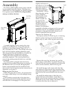
panels first, using two 1/4-20 fasteners for each
panel. Their mounting locations are near the top
and bottom of the panel.
Install the top wing panel last using two 1/4-20
fasteners. The mounting holes are near the inside
edge of the side wing panels.
Before tightening, make sure the outer edges of
the top panel align with the edge of the side pan-
els.
Brass edge trim is added as the last step of install-
ing the wing panels.
7. Mount the side trim panel—each is held in
place by two magnets.
Install the left side trim panel first by placing the
bottom close to where it goes, then align the top
and move it close to the insert body until it is held
snugly by the two magnets.
The right side trim panel installs in the same
fashion as the left, but the wiring (Two Amp Mate-
N-Lok connectors) that serves the On-Off switch at
the top of the panel and the blower speed control
switch on the bottom must be connected first.
Move the right panel close enough to make the
connection. Align the three wire male connector
with the latch to the bottom. Push into the three
wire female connector on the stove until it clicks.
Do the same with the two wire connector with the
latch turned to the top. move panel into place
while routing the switch wires into the opening of
the wing bracket. Secure the panel.
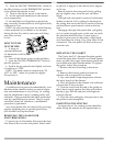
AIR SHUTTER ADJUSTMENT
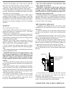
The final step of the installation is to check the
flame pattern, which should resemble the pattern
illustrated in the right column.
The flames should be relatively well-defined and
stable. They should be bright yellow with a blue
base where attached to the burner ports, and
should not look orange or sooty.
Start the fire according to the directions on page
11 and allow the heater to burn for approximately
15 minutes. The flames will increase in length and
become more yellow in color as the unit heats up.
Three adjustment levers—one for each burner—
are used to adjust the flames for a particular
installation. They are accessible when the front
control access door is opened. The levers may
become hot to the touch after prolonged operation.
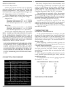
INTO THE FIREPLACE
The Clarity Fireplace Insert has an integrated
draft hood, so a separate draft hood is not re-
quired.
Some fireplace openings may be large enough to
connect the draft hood to the venting after the unit
has been moved to its final position. Some openings
will be too small and will require that the draft
hood first be connected to the venting, and then
guided into position on the top of the insert as the
unit is pushed back into the fireplace.
Particularly in installations with tight clearances,
the procedure will be most easily accomplished if
the trim and wing panels are installed as the last
step.
Follow these steps:
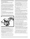
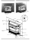
1. Connect the Clarity Insert's detachable draft
hood to the end of the venting by sliding it inside
the venting, then secure it with three sheet metal
screws.
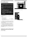
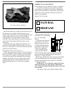
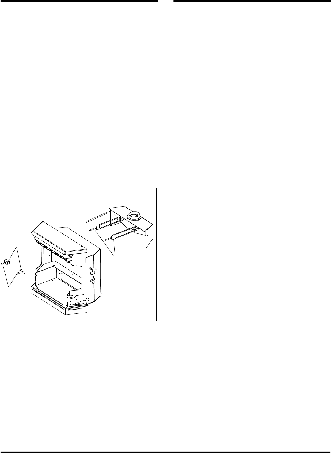
2. Line up the two draft hood guides with the
fourth heat exchanger tube in on each side on the
back of the stove as shown above.
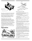
3. With assistance, push the insert back into the
fireplace, while at the same time pulling on the
draft hood to coax it into position. Continue until
both guides are far enough forward that the
retainer clamps and nuts can be installed on the
threaded guide bolts.
4. Tighten the nuts to secure the draft hood.
5. Adjust the rear levelling bolts until the unit is
level.
6. Install the wing panels; they attach to brackets
on each side of the Clarity. Install the side wing
Clamps
Nuts
Guides
Evaluation notes were added to the output document. To get rid of these notes, please order your copy of ePrint IV now.