


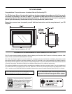

7U32-5 FPI Direct Vent Gas Insert
A
B
D
E
C
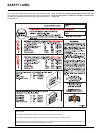
MANUFACTURED
MOBILE HOME
ADDITIONAL
REQUIREMENTS
1) Ensure that structural members are not cut
or weakened during installation.
2) Ensure proper grounding using the #8
ground lug provided.
3) Appliance must be anchored to the fl oor
with the supplied anchoring methods.
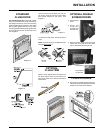
MATERIALS REQUIRED
No electrical power supply is required for the gas
control to operate. A 120 Volt AC power cord is
hooked up to the fan. Plug the 3 wire cord into
a suitable receptacle. Do not cut the ground
terminal off under any circumstances. When
connected with 120 volts, the appliance must be
electrically grounded in accordance with local
codes, current version of CSA C22.1 (in Canada)
or in the absence of local codes, with the National
Electrical Code ANSI/NFPA 70-1987.
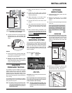
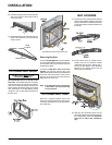
INSTALLATION
INSTALLATION
CHECKLIST
Before installing vent system ensure that the
damper plate is open and secure to prevent the
damper plate from falling down and crushing
the liner.
The FPI Gas Insert is installed as listed.
1) Check all clearances to combustibles, (Refer
to sections "Minimum Fireplace Dimensions
and Clearances to Combustibles)
2) Make the gas connection. (Refer to section
"Gas Connection")
3) Install the 3" flue liner to the sliding
connector plate. (Refer to section "Flue
Liner Installation.")
4) Slide the unit half way into the fi replace.
5) Pull the vent connector plate through the
tapered brackets and fasten to the front plate.
Refer to section "Flue Liner Installation.")
6) Slide the unit fully into the fi replace.
7) Test gas pressure (Refer to section "Gas
Pipe Pressure Testing"). Check aeration
system (Refer to section "Gas Insert Aeration
System").
8) Install standard and optional features. Refer
to the following sections:
a. Brick Panel
b. Lot Set
c. Faceplate & Trim
d. Standard Flush Door
e. Flush Trim
f. Double Screen Door
g. Flush Louvers
h. Bay Louvers
i. Bay Door
j. Bay Trim
k. Full Screen Doors
l. Hampton Cast Faceplate
m. Hampton Cast Grills
n. The Kensington Front
o. Wall Thermostat
p. Remote Control
9) Final check: Before leaving this unit with the
customer, the installer must ensure that the
appliance is fi ring correctly. This includes:
a) Clocking the appliance to ensure the
correct fi ring rate.
b) Adjusting the primary air, if required, to
ensure that the fl ame does not carbon.
See "Gas Insert Aeration System"
section.
c) Ensuring that the appliance is venting
correctly.
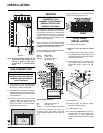
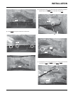
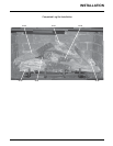
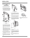
MINIMUM FIREPLACE
DIMENSIONS
The minimum fi replace clearances & dimensions
for the FPI gas insert are shown in the following
diagrams:
Diagram 1
Combustible Mantel Clearances
with Bay & Flush Louvers in
Masonry and Factory Built
Fireplace Installation
Diagram 2
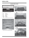
CLEARANCES TO
COMBUSTIBLES
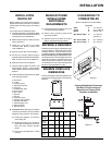
Minimum Clearances to Combustibles
From Unit
Sides A 10" / 255 mm
Ceiling B 47.5" / 1205 mm
Mantel C see Dia. 2 & 3
Max. Mantle Depth G 12" / 305 mm
(see Dia. 2)
Min. Alcove Width K 48" / 1220 mm
Max. Alcove Depth L 36" / 915 mm
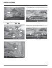
Max Lentil
Bar Depth
A
Height
B
Depth
C
Width
(rear)
D
Width
(front)
E
Regency
Countour
Faceplate
9" 22" 14" 22-1/2" 26-1/2"
Regency
Molded
Faceplate
10" 22" 15" 22-1/2" 29"
Palace
Front
10" 22" 15" 22-1/2" 29"
Hampton
Cast
Faceplate
9" 22" 14" 22-1/2" 26-1/2"
Full
Screen
Doors
9" 22" 14" 22-1/2" 26-1/2"