


26
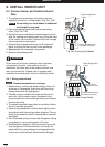
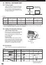
9.4.2 Wire Length and Diameter
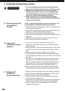
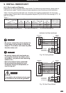
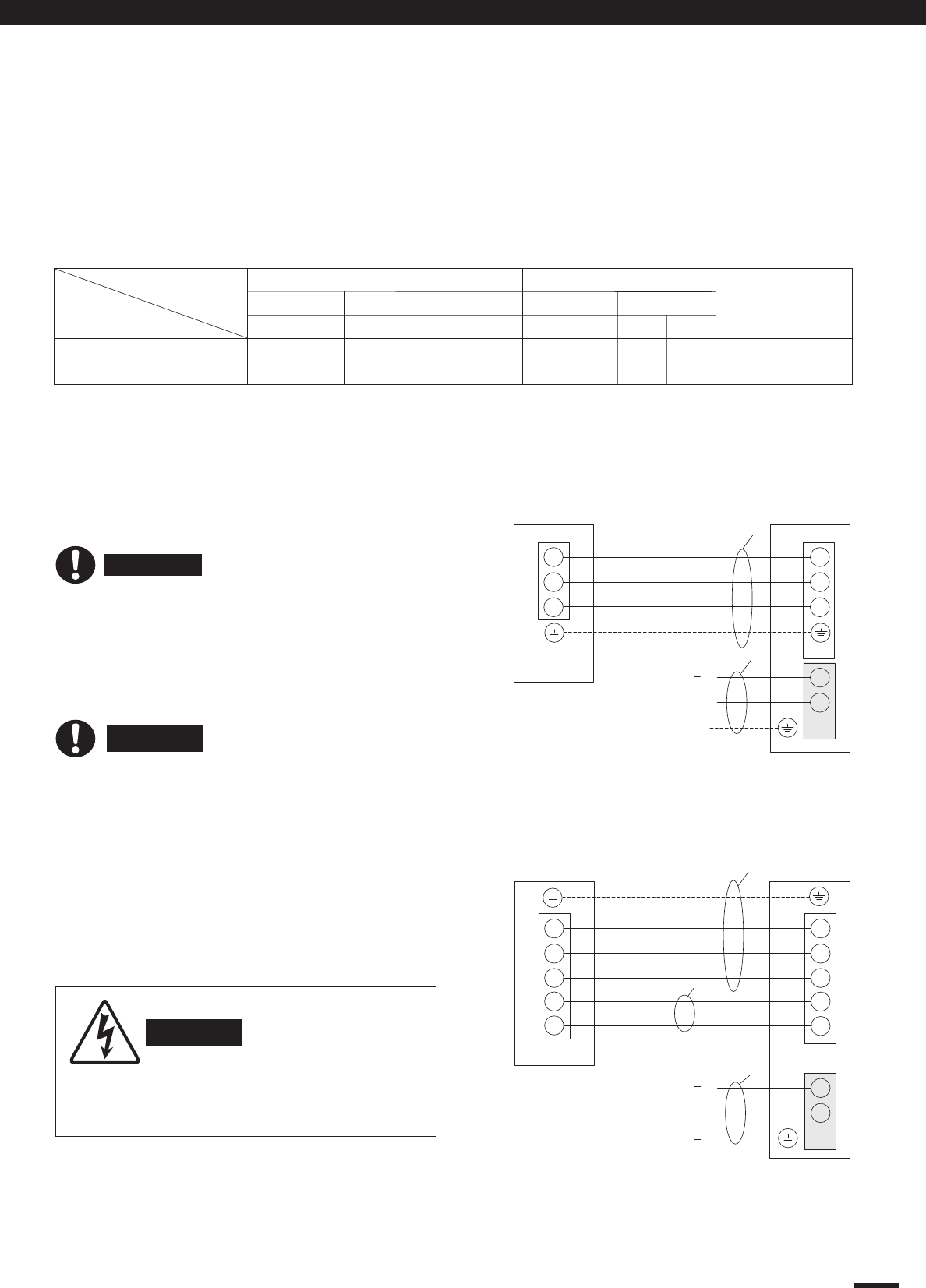
WIRING SYSTEM DIAGRAM
• Be sure to connect the power supply line
to the indoor unit as shown in the wiring
diagram. The outdoor unit draws its power
from the indoor unit.
• Be sure to comply with local codes on
running the wire from the indoor unit to
the outdoor unit (size of wire and wiring
method, etc.).
• Each wire must be firmly connected.
• No wire should be allowed to touch
refrigerant tubing, the compressor, or
any moving part.
To avoid the risk of electric shock, each
air conditioner unit must be grounded.
Regulations on wiring diameter differ from locality. For field wiring requirements, please refer to
local electrical codes. Carefully observe these regulations when carrrying out the installation.
Table 1 lists the recommended and max. allowable wire lengths and diameters for the power
supply system. Please refer to the wiring system diagram (Fig.18 &19) for the meaning of “A”, “B”
and "C" in Table 1.
Fig. 19 (Heat Pump Model)
Grounding Line
OUTDOOR
UNIT
INDOOR
UNIT
2
Terminal
2
N
L
Terminal
Power Supply
Single Phase
220-240VAC 50HZ
L
N
(B)
(A)
P.C.B
Blue
Black
4
N
5
N
4
5
Yellow-Green
(Grounding Line)
Orange
Violet
(C)
*(A) Power supply wiring length (m) ; *(B) Power line length (m) ; *(C) Control line length (m)
Table 1
Cross-sectional
area (mm
2
)
Recommended
Fuse or circuit
breaker capacity
Model 2.5 x (3)
KC18AM 1.8m
32m
20A
*(A)
*(B)
*(C)
(A) + (B)
2.5 x (4) 0.752.5
Max. allowed
5.0m
KC18AGH 1.8m
32m
20A5.0m
*(C)
0.75 x (2)
5.0m
N.A
CAUTION
WARNING
Fig. 18 (Cooling Model)
Grounding Line
OUTDOOR
UNIT
2
Terminal
N(1)
2
N
L
Terminal
Power Supply
Single Phase
220-240VAC 50HZ
L
N
(A)
P.C.B
N(1)
Blue
Black
Brown
(B)
INDOOR
UNIT
WARNING
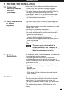
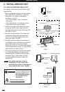
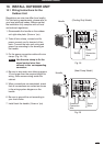
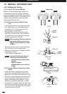
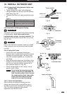
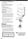
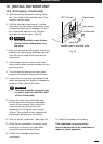
9. INSTALL INDOOR UNIT
Installation Service
20m
20m
N.A
32m
1.0
Yellow-Green
(Grounding Line)
33
3 3
Brown