


19
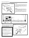
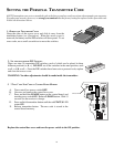
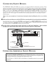
STEP 12:
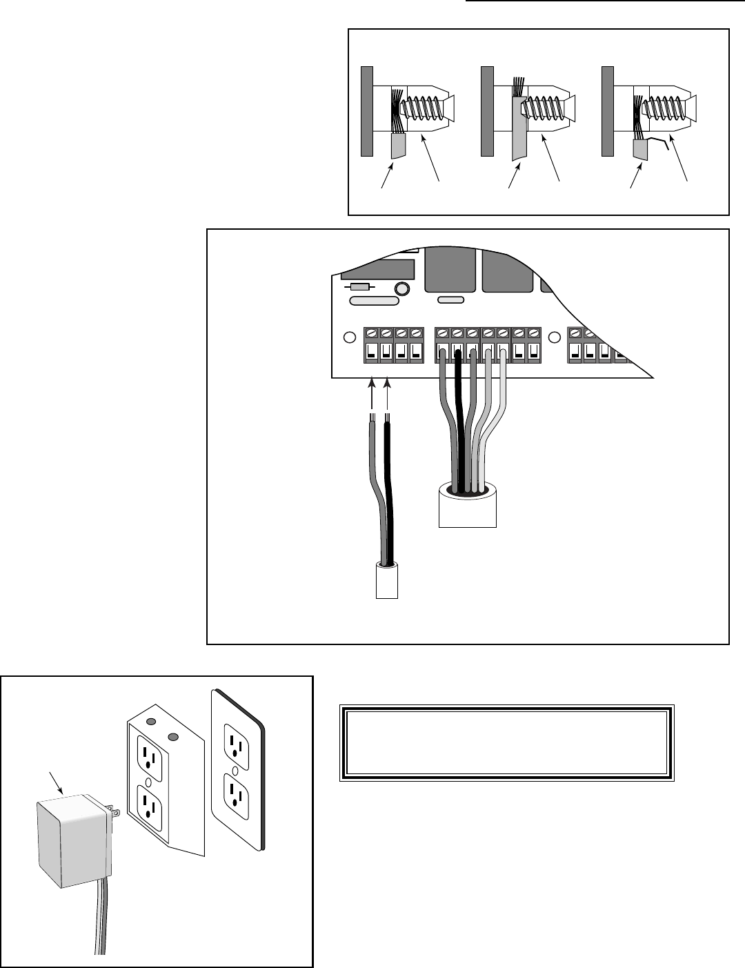
Strip
3
/16" off the ends of the low voltage wire and
twist tightly. These wire ends will be attached to
the control board at the 18VAC terminals located
on the POWER IN terminal block (see Illustration
L). Wire sheathing should not come in contact
with terminals, however, it should not be stripped
so far that wires can come in contact with one
another (see Illustration K).
Insert one transformer wire
into an 18VAC terminal.
Insert the other transformer
wire into the remaining
18VAC terminal (see
illustration L). Transformer
wires can be connected to the
18VAC terminals regardless
of color.
Tighten set screws against
exposed end of wires (see
Illustration K). A dab of
household petroleum jelly on
each wire end will help
prevent corrosion.
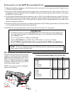
The ACCESSORY terminal
block provides the connection
point for safety loops, wands,
push buttons, intercoms, card
readers, etc. See page 27 for
more information about
connecting accessories.
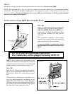
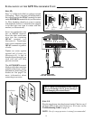
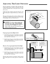
STEP 13:
Plug the transformer into the electrical outlet. Check to see if
the green LED on the control board is on. If it is not, see the
Troubleshooting Guide on page 30.
NOTE: Use of a surge protector is strongly recommended.
SURGE PROTECTOR
Transformer
HINT: Keep a few mothballs in the control
box to discourage insects from entering it
and damaging the control board.
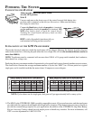
INSTALLATION OF THE GTO TRANSFORMER CONT.
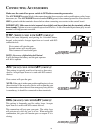
Illustration L
Correct
Wrong Wrong
Wire
Terminal
Block
Terminal
Block
Terminal
Block
Wire Wire
Illustration K
FIRST OPERATORPOWER IN
18VAC SOLAR
~~– +
RED
BLK
ORG
BLU
GRN
CLS EDG
OPN EDG
RE
RED
BLACK
RED
BLACK
Power Cable
from First Operator
Low Voltage Wire
from AC Transformer
SECOND OPER