


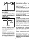
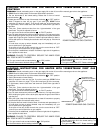
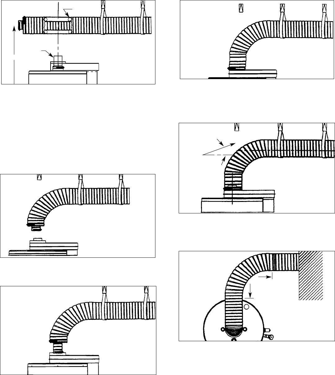
SLOPE
Figure 3 J
Check the vent pipe’s level or slope again, and adjust if
required.
– 4 –
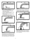
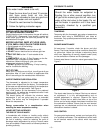
Figure 3 F
Bend the 3 1/8” and 6” corrugated pipe all together
toward the water heater’s flue connection.
Figure 3 G
Pull and connect the 3 1/8” corrugated pipe to the water
heater’s flue tube reducer with hi-temp red silicone and gear
clamp. Make sure this connection is tight and leak proof.
*The sealant between 3 1/8” corrugated pipe and water
heater’s flue tube reducer must be hi-temp red silicone
or other material suitable for 600°F continuous service.
Figure 3 H
Apply silicone around 6” collar on air manifold box. Pull
corrugated vent tube all the way on to collar and secure
with one sheet metal screw (approx. 3/4”) up from edge
of vent tube. Pull gear clamp past screw and tighten.
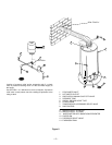
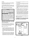
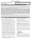
Figure 3 E - Pull the 3 1/8” and 6” Corrugated Pipe
Toward the Water Heater Individually.
1. Pull the 3 1/8” corrugated pipe toward the water
heater and leave some length over the water
heater’s center for bending.
2. Pull the 6” corrugated pipe toward the water heater
and leave it 1” shorter than 3 1/8” pipe.
3. Make sure there are two springs evenly spaced at
the bend in the pipe.
4. Use metal hangers to keep vent pipe level or with a
slope upward from the heater to terminal.
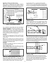
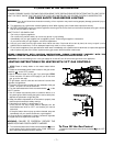
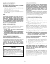
REDUCER
TOP VIEW
90°
MAXIMUM
BEND
Figure 3 K - CONDITION 1
Where a straight vent pipe arrangement is impossible, a
horizontal 90 degree maximum bend can be made. Use
the water heater casing outer diameter as a template to
form the corrugated pipe.
H
SPRING
Offset vent pipe Arrangement