


– 3 –
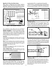
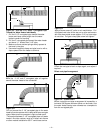
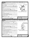
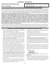
Figure 3 - Vent Location Limitations
For a second or more direct vent unit, the distance
between vent terminals must have a minimum of 1 foot.
INSPECT SHIPMENT –– There may be hidden damage
caused by transit. Check to be certain all parts of the
venting system, as shown in Figures 3A through 3M, are
present. Inspect the upper and lower air inlet boxes, rear
air tube and all parts of the venting system.
CAUTION
If there are any damaged parts, DO NOT install this water
heater. Report any shortage to your distributor or damage
to your carrier.
Note: The four fasteners that are required to secure the
vent terminal to the exterior wall are not provided. These
should be screw type (not nails) chosen for the type of
construction and obtained locally.
CAUTION
Cut edges of corrugated (flex) pipe are extremely sharp.
Wear gloves when handling.
VENT CONNECTIONS - After the location for the vent
terminal has been selected as outlined in Figure 3, use
the following illustrations for installation:
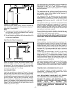
7” DIAMETER
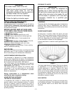
Figure 3 A - Locating Clearance Hole for Vent.
Cut a clearance hole, approximately 7 inches in diameter,
through the exterior wall for the vent assembly. The
minimum height should not be less than 68” from the hole
center to bottom of water heater. The maximum height
recommended is 90” or in compliance with figure 3M.
*Where the wall is combustible and the wall thickness is
over 14”, 1 inch clearance to combustible materials around
the terminal pipe is needed. The first 14” is zero clearance.
MIN.
68”
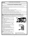
Vent Terminal must be located at
least 12” from Windows, Doors,
or any other Opening through
which flue gases could enter the
building.
Any Forced Air Inlet
into the building
Vent Terminal must be located at least 18”
from any overhang or building corner or
other irregularity.
12” Min. above grade. Higher
in Areas of Heavy Snowfall
Within 10 feet
36”
Min.
12” Min.
Vent terminal must be
located at least 36” above
any Forced Air Inlet into the
building within 10 feet of
the Vent Terminal
18”
Min.
18”
Min.
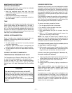
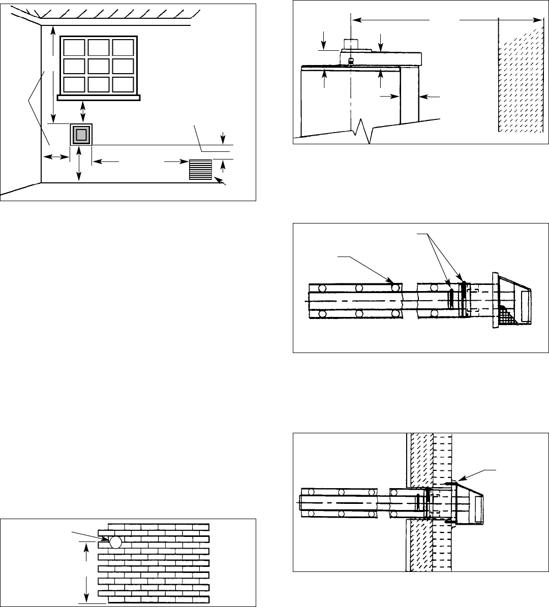
Figure 3 C - Vent Assembly.
The vent pipe and terminal are assembled by the
manufacturer as shown in figure 3C. There are springs
fastened inside the corrugated pipe. When the vent pipes
are pulled to a required length, the distances between the
springs will still be equally spaced.
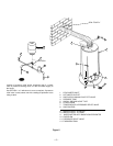
Figure 3 B - Moving Water Heater To Its Final
Installed Location.
Move the water heater to its final installed location. Make
certain clearances from combustible material are
observed. The maximum distance from center of water
heater to outside wall should not be longer than 90”.
MAX. 90”
3”
4”
4”
WALL
CLAMP
SPRING
Specially For Direct Vent Water Heater:
Make certain to observe the vent location limitations
complying with the CAN/CGA-B149 Installation Code or
ANSI Z223.1 National Fuel Gas code and/or local codes.
There are some important issues shown in Figure 3.
BOTTOM OF HEATER
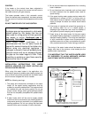
Figure 3 D - Securing Vent Termination Assembly To
The Exterior Wall.
Introduce the 6” pipe through the clearance hole from
exterior wall then secure the vent terminal to the exterior
wall with 4 screw anchors appropriate for the type of
wall construction. Caulk the junction of the vent terminal
base plate and the exterior wall with exterior type
silicone sealant.
SEALANT