


92
Fan and Heater
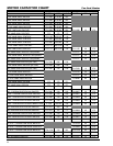
Control Board Comments
Gas Valve Relay
Current Ratings:
A) 05-14X201-00X Common relay output
05-14X401-00X 120VAC 1 amp
B) 05-14X301-00X Isolated valve contacts
05-14X501-00X 1) 24VAC 2amps
2) 120VAC 1amps
3) 240VAC 0.5amps
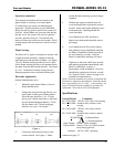
Timing
(Trial -for-Ignition)
-000: 3.3 seconds
-001: 4.7 seconds
-005: 10 seconds
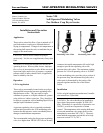
Electrodes
05-100000-XXX*: Gap 0.125" = 0.031"
or
22-100000-XXX*:
*Last three digits designate configuration
Lead Wire
05-125978-0XX**: High Voltage
05-125979-0XX**: Low Voltage
CAUTION: If ambient temperature ratings are
exceeded, damage to the unit and/or improper
operation may result.
** Last Two digits designate length of wire in
inches. EX: -024 = 24 inches. When ordering,
specify length required.
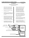
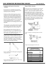
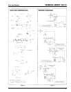
Wiring
IMPORTANT: The model number of each
Fenwal Spark Ignition Module is stamped on a lable
attached to the high voltage transformer. Select the
electrical ciruit diagram in Figure 3 which matches
the model number on the high voltage transformer
and wire the unit accordingly.
NOTE: The burner and the 120V suppy (NEUT-
L2) must be grounded to obtain satisfactory opera-
tion. Failure to do so will prevent ignition from
lasting beyond the trial for ignition period.
Fenwal Gas Ignitors are provded with 1/4" male
quick connect terminals (ARK-LES Part No. 300
H19A or recommended equivalent should be used
for all connections.) When making connections, be
Warning: Do not apply power to imput terminals
unless electrode is properly connected and
grounded or damage to the unit may result.
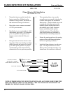
System Checks
Preliminary System Checks
It is desireable to checks the system after installa-
tion and before gas supply is turned on.
Be sure that the input is polarized as shown on
wiring diagrams and the installation is electrically
grounded. Cabinet, electrode and burner must
have a common ground. Connect as shown in
proper diagram in Figure 3, page 73.
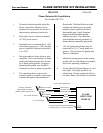
Polarity Check
1. With voltmeter or indicator light,
measure from Terminal A (L1) to ground.
Voltage should be 120V.
2. Measured from L2 to ground. Voltage
should be "0".
3. If 1 and 2 above are opposite, reverse
input leads to insure correct polarity.
Initial Operation
1. Check installation, mounting and elec
trode gap to insure conformance to
specifications.
V
sure they conform to both U.L. and local codes.
NOTE:High voltage lead wire should be routed at
least 1 inch from metal piping or metal frames.
Do not wrap or bundle any wires with or against
the high-voltage lead wire.
CAUTION: HIGH VOLTAGE
NOTE: Although epoxy coated to insure proper
operation at 90% relative humidity, good electrical
practice should be followed. Insure the control is
mounted so that total water immersion will not
result. If such a condition occurs, unit should be
cycled to the OFF position and inspected by a
qualified service person before recycling.
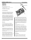
FENWAL-SERIES 05-14
continued on page 74