


88
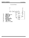
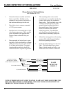
Fan and Heater
SELF-OPERATED MODULATING VALVES
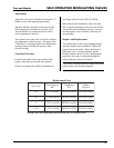
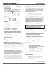
Orifice Sizes in Kit
Number PLG14A-600R
Orifice Size Color
In. mm Code
.040 1.02 Red
.062 1.57 Yellow
.078 1.98 Green
.093 2.36 Blue
.125 3.18 Aluminum
Solid Plug Brass
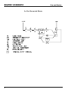
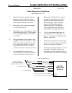
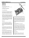
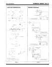
If the installation requires that the bulb be in a
horizontal position, it is very importanat to be sure
that the word "TOP" appears at the top or upper-
most surface of the bulb. (see Figure 4).
CAUTION: Do not kink or sharply bend the
capillary tubing. Coil and secure excess capillary
if installed where subjectd to vibration, allowing
some slack in capillary to avoid "violin string"
vibrations. Do not allow capillary to rub surfaces
where friction can damage the tubing.
Installation and Operation Instructions,
continued
Be sure the valve is installed so the gas flows
through the body in the proper direction as indi-
cated by the arrow on the body.
On direct or indirect fired vaporizer systems in
which hot LP gas is flowing through the valve,
install the valve with the bellows pointing down.
This allows the temperature sensing element to
perform properly. In vapor withdrawal systems,
the gas flowing through the valve is cooler than
the sensing bulb and valve is cooler thatn the
sensing bulb and valve mounting position is not as
important.
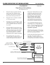
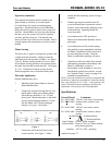
The temperature sensing bulb should be installed
so the capillary end of the bulb is always higher
than the plugged and of the bulb (see figure 3.)
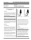
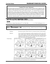
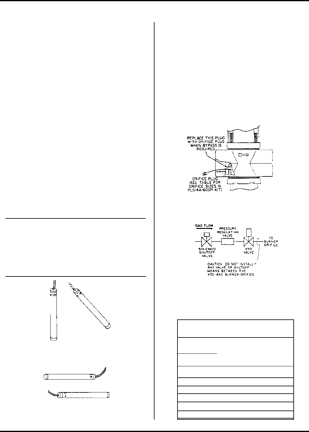
Bypass Orifice Selection
These valves have a threaded hole in the internal
web of the valve for an internal bypass. ( See
figure 5) They are normally supplied with a solid
plug installed in this hole for complete shutoff.
Five drilled orifice fittings are supplied with each
valve for field installation, if bypass is needed. The
bypass orifice is ued to maintain a minimum flame
which will burn even when the close-off point has
been reached. When bypass is required, remove
the solid plug and replace with the proper orifice
plug. See selection table.
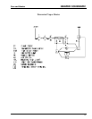
Figure 3-Capillary-end of bulb higher than plugged-end
of temperature bulb.
Figure 4-Horizontal bulb mounting with "TOP" at top
or uppermost surface of bulb.
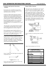
Figure 6-Typical piping for the V50 Valve
Figure 5-Cutaway view showing location of orifice
plug