


85
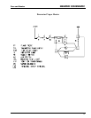
Fan and Heater
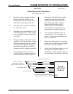
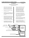
FLAME DETECTOR KIT INSTALLATION
1994-1995
Flame Detector Kit Installation
Part Number HF-7136
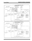
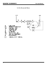
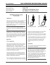
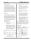
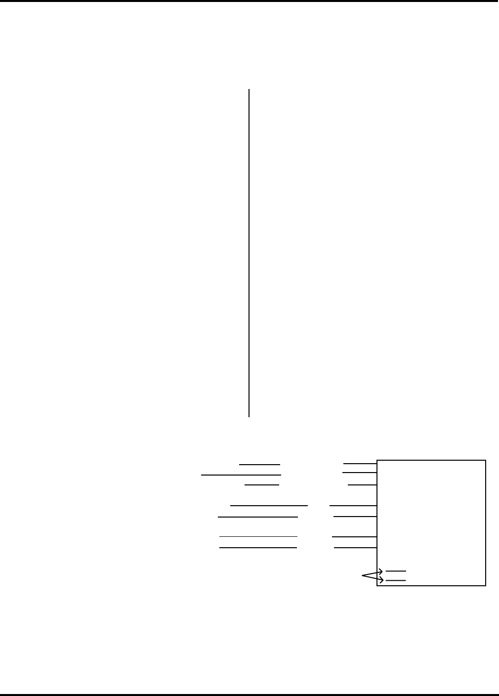
1. Mount the detector module inside the
heater control box. Module can be
mounted in any position, but install so
that moisture cannot get inside unit.
2. Run white wire to common or neutral
of 120V power source.
3. Run black wire to terminal that is 110V
when heater gets power. (Wire module
power in parallel with main solenoid if
it is 110V.)
4. Run green and red wires down to sens-
ing probe. Red wire should go to flame
probe electrode and green wire should
go to flame probe ground. For proper
operation the ground wire should be
connected as close to probe as possible.
5. The remaining three wires are the
normally open or normally closed relay
contacts that replace the mechanical
flame probe. The blue-black wire is the
common, the white-brown wire is the
normally closed, and the white-blue is
the normally open. On all Airstream
heaters use the blue-black and the
white-brown wires. The white-blue
wire should be used only on makes of
heaters that use a normally open probe.
6. 110 volt igniton transformer may be
connected to (2) 1/4" male spade con-
nectors. This will turn off igniton after
flame is established.
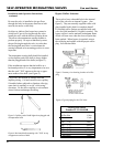
7. Mount the sensing probe so the sensing
portion will be in the flame at its highest
and lowest operating conditions.
8. On the side of the flame detector is a red
neon light. This light should be on
when flame is being sensed and will go
out when flame out condition is detected.
PNEG-286
FLAME
DETECTOR
MODULE
CONNECT WHERE
MECHANICAL PROBE
WIRES WERE CONNECTED
NORMALLY OPEN WHITE/BLUE
COMMON BLUE/BLACK
NORMALLY CLOSED WHITE/BROWN
V
TO FLAME SENSOR
ELECTRODE RED
GROUND GREEN
V
TO 110V POWER
BLACK
WHITE
V
110 VOLT IGNITION TRANSFORMER
CONNECTION (1/4" MALE SPADES)
(NOT USED NORMALLY)