


87
Fan and Heater
SELF-OPERATED MODULATING VALVES
Series V50
Self-Operated Modulating Valves
For Outdoor Crop Dryer Service
Johnson Controls, Inc.
Control Products Division
1302 East Monroe Street
Goshen, IN 46526
Installation and Operation
Instructions
Application
These valves control the flow of gas on natural or LP
gas fired outdoor crop dryers to maintain desired
drying air temperature. Changes in air temperature at
the sensing bulb cause the valve to modulate the gas
supply to the main burner.
CAUTION: Valves are for outdoor crop dryer
service only. Not for use on applications of any other
kind.
All Series V50 valves are designed for use only as
operating devices. Where system closure, improper
flow or loss of pressure due to valve failure can result
in personal injury and/or loss of property, a separate
pressure relief or safety shutoff valve, as applicable,
must be added by the user.
Operation
LP Gas Application
These valves are normally located on the crop dryer
gas manifold between the pressure regulating valve
and the burner orifice. They are used on vapor
withdrawal systems or on liquid withdrawal systems
using a direct or indirect vaporizer. They should not
be used as a expansion valves (handling liquid LP) on
straight liquid withdrawal systems.
A pressure regulating valve is required to maintain
uniform inlet pressure to the V50 modulating valve
because the tank pressure varies considerably due to
changes in tank ambient temperature.
The recommended setting for the pressure regulating
valve is no higher than 30PSIG (207 kPa) as in many
instances the outside temperature will not be high
enough to provide the regulating valve with
pressure above this value. The maximum working
pressure for V50 self-operating valves is 30 PSIG.
As the modulating valve provides only a portion of
the pressure drop, the maximum firing rate (valve
wide open) is determined by the setting of the
pressure regulator and the size of the burner
orifice.
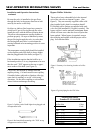
Installation
Follow original equipment manufacturer's installa-
tion instructions, if provided.
CAUTION: The valve should not be installed on
lines where line pressure excedds 30 PSIG (207
kPa). When there is a possibility of pressures over
30 PSIG, provide an overpressure or alarm
control. The temperature at the sensing bulb must
not exceed maximum valve range shown on the
nameplate by more than 20F° (10C°). The maxi-
mum ambient temperature around the valve body
must nots exceed 175°F (79°C).
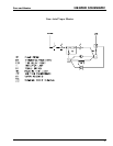
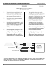
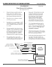
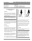
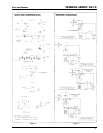
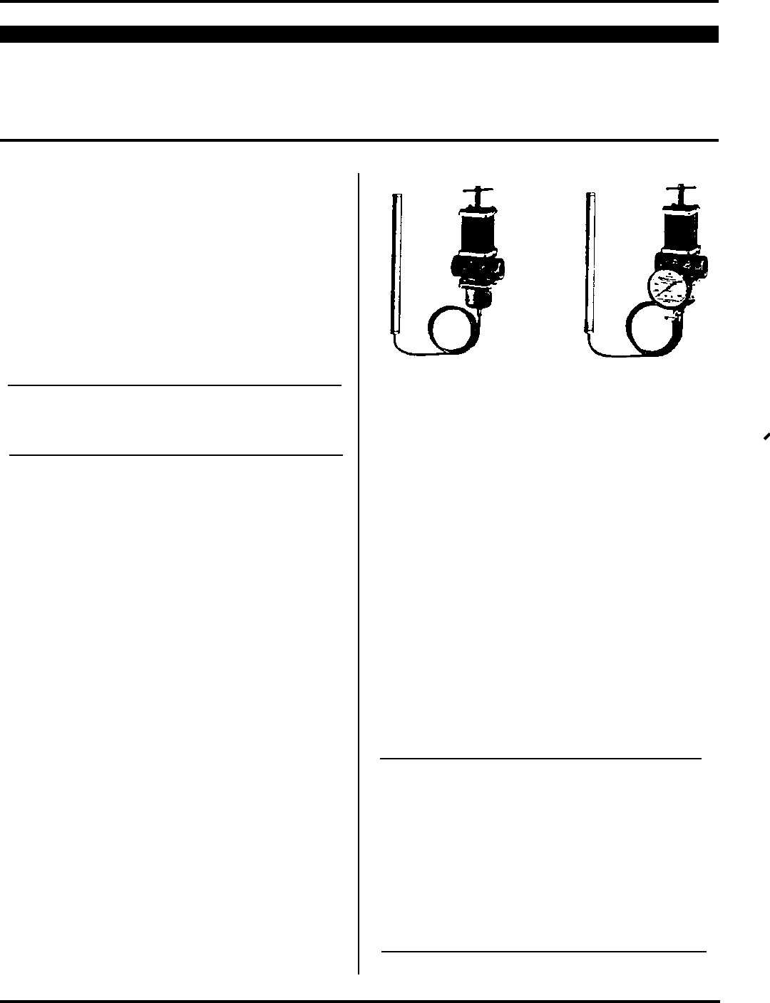
Figure 1
Modulating Value V50A
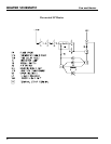
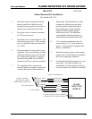
Figure 2
Modulating Value V50B