


Installation
6 309967C
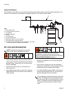
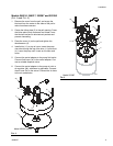
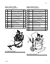
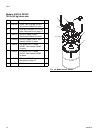
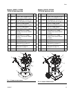
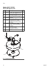
Typical Installation
The installation shown below is only a guide for selecting and installing system components and accessories. Con-
tact your Graco distributor for assistance in designing a system to suit your particular needs.
Air Line and Accessories
• Install a pump runaway valve (G) to shut off the air
to the pump if the pump accelerates beyond the pre-
adjusted setting. A pump that runs too fast can be
seriously damaged.
• Install an air line lubricator (F) for automatic air
motor lubrication.
• Install a bleed-type master air valve (H) to relieve air
trapped between the valve and the motor when the
valve is closed.
• Install the air regulator (C) to control pump speed
and pressure.
• On the main air supply line from the compressor,
install an air line filter (E) to remove harmful dirt and
contaminants fro the compressed air supply.
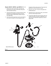
• For models 253384 through 253390, install the pro-
vided air regulator/safety valve (K) at the pump air
inlet with the nipple (9a, also included).
Key:
A Fluid dispense line
B Pump ground wire (required)
C Air regulator
D Main air supply line
EAir filter
F Pump lubricator
G Pump runaway valve
H Bleed-type master air valve (required)
J Quick-disconnect couple and nipple
K Air regulator (9b) with safety valve (9c) and gauge (not shown)
Included with models 253384 through 253390
A
C
D
F
G
H
J
E
01519
B
NOTE: Install air line accessories in the order
shown in the Typical Installation illustration.
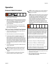
Trapped air can cause the air motor to cycle
unexpectedly, causing serious injury if you are
adjusting or repairing the pump. Be sure to follow the
Pressure Relief Procedure on page 11.
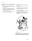
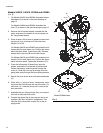
Avoid hanging air accessories directly on the pump
air inlet. The fittings are not strong enough to sup-
port the accessories and may cause one or more to
break. If accessories must be installed directly on
the pump, provide a bracket on which to mount
them.