


308-739 7
Installation
System Accessories
WARNING
A
bleed-type master air valve (D) and a fluid drain
valve (J) are required in your system. These
accessories help reduce the risk of serious injury
including fluid injection, splashing in the eyes or on
the skin, and injury from moving parts if you are
adjusting or repairing the pump.
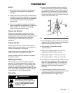
The bleed-type master air valve relieves air trapped
between this valve and the pump after the air is
shut of
f. T
rapped air can cause the pump to cycle
unexpectedly
. Locate the valve close to the pump.
Order Part No. 1
13–333.
The fluid drain valve assists in relieving fluid pres
-
sure in the displacement pump, hose, and gun.
T
riggering the gun to relieve pressure may not be
suf
ficient. Order one of the following:
Part No.
Description
238–635
1/4 npt (mbe), carbon steel
210–657
1/4 npt (mbe), carbon steel
210–658
3/8 npt (mbe), carbon steel
210–659
1/4 npt x 3/8 npt (mbe), carbon steel
239–018
1/4 npt (mbe), stainless steel
235–992
1/4 npt x 3/8 npt (mbe), stainless steel
Air and Fluid Hoses
Be sure all air and fluid hoses are properly sized and
pressure-rated for your system. Use only electrically
conductive air and fluid hoses. Use a 13 mm (1/2 in.)
I.D. (minimum) air hose (H) to supply air to the pump.
Fluid hoses must have spring guards on both ends.
Connect a fluid hose (L) to the pump’
s 3/8 npt(f) fluid
outlet. Use of a short whip hose between the main
fluid hose and the gun (M) allows freer gun movement.
Connect a fluid suction hose or tube (N) to the pump’
s
3/4 npt(m) fluid intake.
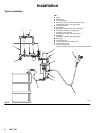
Air Line Accessories
Install the following accessories in the order shown in
Fig. 2, using adapters as necessary:
D
Air line lubricator (C)
Provides automatic air motor lubrication.
D
Bleed-type master air valve (D)
Required in your system to relieve air trapped
between it and the air motor when the valve is
closed (see the
WARNING
at left). Be sure the
bleed valve is easily accessible from the pump, and
is located
downstream
from the air regulator (E).
D
Air regulator (E)
Controls pump speed and outlet pressure by
adjusting the air pressure to the pump. Locate the
regulator close to the pump, but
upstream from the
bleed-type master air valve (D).
D
Pump runaway valve (R)
Senses if the pump is running too fast and shuts of
f
the air supply to the motor
. A pump which runs too
fast can be seriously damaged.
D
Air line filter (F)
Install an air line filter (F) and a moisture trap and
drain valve (P) to help remove moisture and
contaminants from the compressed air supply
.
D Second
bleed-type air valve (G)
Isolates the air line accessories for servicing.
Locate upstream from all other air line accessories.
Fluid Line Accessories
Install the following accessories in the positions shown
in Fig. 2, using adapters as necessary:
D Fluid drain valve (J)
Required in your system to relieve fluid pressure in
the hose and gun (see the
WARNING
at left).
Install the drain valve so that it points down and the
handle points up when it is opened.
D Fluid filter (K)
Filters harmful particles from the fluid.
D Spray gun (M)
Dispenses the fluid. The gun shown in Fig. 2 is an
airless spray gun.