


308-739 11
Service
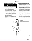
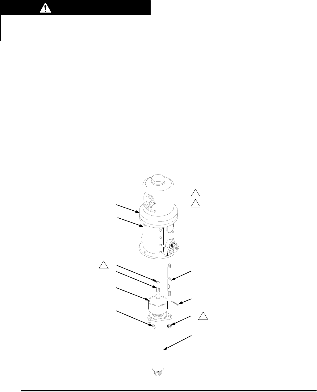
Disconnecting the Displacement Pump
WARNING
To
reduce the risk of serious injury whenever you
are instructed to relieve pressure, always follow the
Pressure Relief Procedure
on page 8.
1.
Flush the pump if possible. Stop the pump at the
bottom of its stroke. Relieve the pressure.
2.
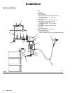
Disconnect the air and fluid hoses. Remove the
pump from its mounting. Note the relative position
of the fluid outlet (S) to the air inlet (T). See Fig. 3.
3.
Unscrew the tie rod locknuts (4) from the tie rods
(3). Remove the cotter pin (5). Carefully pull the
displacement pump (2) of
f the air motor (1).
Unscrew the displacement rod (U) from the air
motor (1). Inspect the o-ring (6).
4.
Refer to manual 306–981 for displacement pump
service. T
o service the air motor
, refer to manual
307–043.
Reconnecting the Displacement Pump
1. Lubricate
the o-ring (6) and check that it is in place
on the displacement rod (U).
2.
Orient the fluid outlet (S) to the air inlet (T) as
noted in step 2 under
Disconnecting the
Displacement Pump
.
Position the displacement
pump (2) on the tie rods (3). See Fig. 3.
3.
Screw the displacement rod (U) into the shaft of
the air motor (1) until the pin holes are aligned.
Install the cotter pin (5). Screw the locknuts (4)
onto the tie rods (3) loosely
.
4.
Mount the pump and reconnect all hoses.
Reconnect the ground wire if it was disconnected
during repair
. T
ighten the packing nut (V). Fill the
wet-cup with Graco Throat Seal Liquid or
compatible solvent.
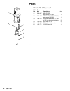
5. T
ighten the tie rod locknuts (4) evenly
, and torque
to 20 to 27 N
S
m (15 to 20 ft–lb). Start the pump
and run it at about 2.8 bar (0.28 MPa, 40 psi) air
pressure, to check that it is operating properly
.
1
2
Lubricate.
Torque
to 20 to 27 N
S
m (15 to 20 ft-lb).
Fig.
3
07197
4
6
3
1
2
5
S
T
U
V
1
2