


308-739 5
Installation
NOTES:
D
Reference numbers and letters in parentheses in
the text refer to the callouts in the figures and
drawings.
D
Always use Genuine Graco Parts and Accessories,
available from your Graco distributor
. If you supply
your own accessories, be sure they are adequately
sized and pressure-rated to meet the system’
s
requirements.
D
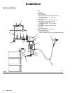
Fig. 2 is only a guide for selecting and installing
system components and accessories. Contact your
Graco distributor for assistance in designing a
system to suit your particular needs.
Prepare the Operator
All
persons who operate the equipment must be
trained in the safe, ef
ficient operation of all system
components as well as the proper handling of all fluids.
All operators must thoroughly read all instruction
manuals, tags, and labels before operating the
equipment.
Prepare the Site
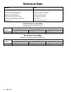
Ensure
that you have an adequate compressed air
supply
. Refer to the performance chart on page 15 to
find the air consumption of your pump.
Keep the site clear of any obstacles or debris that
could interfere with the operator
’
s movement.
Have a grounded, metal pail available for use when
flushing the system.
Mounting the Pump
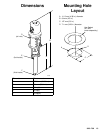
Mount
the pump (A) to suit the type of installation
planned. The pump dimensions and mounting hole
layout are shown on page 13. If you are using a wall
bracket (B), check that the wall is strong enough to
support the weight of the equipment, hoses, fluid, and
stress caused when the pump is in operation. Mount
the wall bracket 1.5 m (5 ft) above the floor
.
Grounding
WARNING
FIRE AND EXPLOSION HAZARD
Before operating the pump, ground the
system as explained below
. Also read
the section
FIRE AND EXPLOSION
HAZARD
on page 4.
D
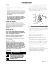
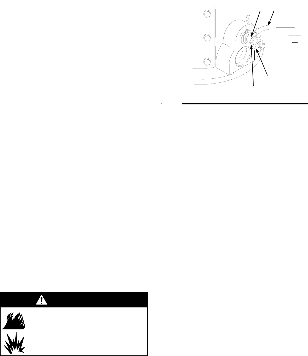
Pump:
Use a ground wire and clamp. See Fig.1.
Loosen the grounding lug locknut (W) and washer
(X). Insert one end of a 12 ga (1.5 mm
@) minimum
ground wire (Y) into the slot in lug (Z) and tighten
the locknut securely
. Connect the other end of the
wire to a true earth ground. For a ground wire and
clamp, order Part No. 237–569.
02464
W
Y
X
Z
Fig. 1
D
Air and fluid hoses:
Use only electrically conductive
hoses with 150 m (500 ft) maximum combined hose
length to ensure grounding continuity
.
D
Air compressor:
Follow manufacturer
’s
recommendations.
D
Spray gun or dispensing valve:
Connect to a
properly grounded fluid hose and pump.
D
Object being sprayed:
Follow your local code.
D
Fluid supply container:
Follow your local code.
D
Solvent pails used when flushing:
Follow your local
code. Use only metal pails, which are conductive,
placed on a grounded surface. Do not place the
pail on a nonconductive surface, such as paper or
cardboard, which interrupts the grounding
continuity.
D
T
o maintain proper grounding continuity when
flushing or relieving pressure,
always hold the metal
part of the spray gun firmly to the side of a
grounded
metal
pail, then trigger the gun.