


Performance Charts
312376L 33
Performance Charts
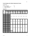
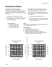
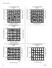
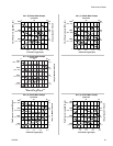
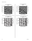
Calculate Fluid Outlet Pressure
To calculate fluid outlet pressure (psi/MPa/bar) at a spe-
cific fluid flow (gpm/lpm) and operating air pressure
(psi/MPa/bar), use the following instructions and pump
data charts.
1. Locate desired flow along bottom of chart.
2. Follow vertical line up to intersection with selected
fluid outlet pressure curve. Follow left to scale to
read fluid outlet pressure.
Calculate Pump Air Flow/Consumption
To calculate pump air flow/consumption (scfm or
m
3
/min) at a specific fluid flow (gpm/lpm) and air pres-
sure (psi/MPa/bar), use the following instructions and
pump data charts.
1. Locate desired flow along bottom of chart.
2. Follow vertical line up to intersection with selected
air flow/consumption curve. Follow right to scale to
read air flow/consumption.
Key: Air Pressure
A 100 psi (0.7 MPa, 7 bar)
B 70 psi (0.5 MPa, 5.0 bar)
C 40 psi (0.3 MPa, 2.8 bar)
D 90 psi (0.63 MPa, 6.3 bar)
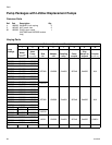
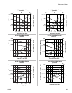
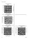
Note:
Use the following key to determine which fluid is presented in the
corresponding performance charts.
Key:Test Fluid
E No. 10 weight oil
F 100,000 centipoise sealant test fluid
G 4,000,000 centipoise silicon test fluid
H 4,000,000 centipoise weldable rubber base sealer
J 8,000,000 centipoise pseudoplastic (expandable plastisal
sealer (500,000 centipoise at flow conditions))
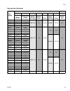
05:1 (E) Check-Mate Pumps
11:1 (E) Check-Mate Pumps
Fluid Pressure in psig (MPa, bar)
Fluid Flow in gpm (lpm)
0
cycles/min
30
60
0
Air Flow in SCFM (m
3
/min)
0.2
(0.8)
0.4
(1.5)
0.6
(2.2)
100
(0.7, 7)
300
(2, 21)
500
(34, 3.4)
700
(4.8, 48)
A
B
C
A
B
C
cycles/min
30
60
0
Fluid Pressure in psig (MPa, bar)
Air Flow in SCFM (m
3
/min)
Fluid Flow in gpm (lpm)
0
0.8
(2.2)
200
(1.4, 14)
600
(4.1, 41)
1000
(6.8, 68)
1400
(9.6, 96)
0.2
(0.8)
0.4
(1.5)
0.6
(2.2)
0.8
(2.2)
2
(.06)
5
(0.1)
8
(0.2)
12
(0.3)
4
(0.1)
11
(0.3)
17
(0.5)
25
(0.7)