


Installation
8 332317C
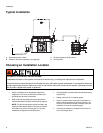
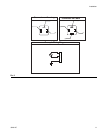
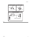
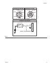
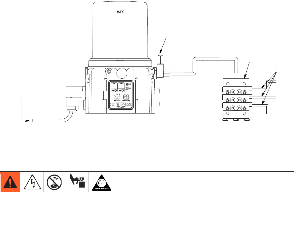
Typical Installation
A Connected to fuse / power
B Pressure relief valve (required, user supplied)
C Series progressive divider valves
D To lube points
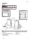
Choosing an Installation Location
• Select a location that will adequately support the
weight of the G1 Pump and lubricant, as well as all
plumbing and electrical connections.
• Refer to the two mounting hole layouts provided in
the Mounting Pattern section of this manual, page 33.
NOTE: The two mounting hole layouts provided in the
Technical Data section show the only correct installa-
tion patterns to use for mounting the G1. No other
installation configurations should be used.
• Use designated mounting holes and provided config-
urations only.
• Always mount the G1 oil models upright.
• If the G1 grease model is going to be operated in a
tilted or inverted position for any period of time, you
must use a model that includes a follower plate, oth-
erwise the G1 must be mounted upright.
• Use the three fasteners (included) to secure the G1
to the mounting surface.
A
B
D
C
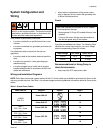
AUTOMATIC SYSTEM ACTIVATION HAZARD
Unexpected activation of the system could result in serious injury, including skin injection and amputation.
This device has an automatic timer that activates the pump lubrication system when power is connected or when exit-
ing the programming function. Before you install or remove the lubrication pump from the system, disconnect and iso-
late all power supplies and relieve all pressure.