


6 308652
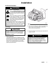
Installation
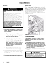
Air Lines
WARNING
Bleed-Type Master Air Valve and Fluid Drain
Valve
A bleed-type master air valve and a fluid drain
valve are required on your system.
The bleed-type master air valve relieves air
trapped between itself and the pump. Trapped air
can cause the pump to cycle unexpectedly, which
could result in serious bodily injury, including
splashing in the eyes, injury from moving parts, or
contamination from hazardous fluids.
The fluid drain valve reduces the risk of serious
bodily injury, including splashing in the eyes or on
the skin, or contamination from hazardous fluids.
Install the fluid drain valve close to the pump’s
fluid outlet to relieve pressure in the hose if the
hose becomes plugged.
1. Mount the air line accessories on the wall or on a
bracket. Be sure the air line supplying the acces-
sories is grounded.
a. The pump speed can be controlled in one of
two ways: To control it on the air side, install
an air regulator. To control it on the fluid side,
install a fluid valve near the outlet.
b. Install a bleed-type master air valve down-
stream from the air regulator, and use it to re-
lieve trapped air. See the Bleed-Type Master
Air Valve and Fluid Drain Valve warning
above. Locate another bleed-type master air
valve upstream from all air line accessories,
and use it to isolate the accessories during
cleaning and repair.
c. The air line filter removes harmful dirt and
moisture from the compressed air supply.
2. Install a flexible air hose between the accessories
and the pump air inlet. Screw the air line fitting
into the air inlet.
3. Do not restrict the exhaust port. Excessive ex-
haust restriction can cause erratic pump operation.
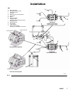
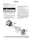
Fluid Lines
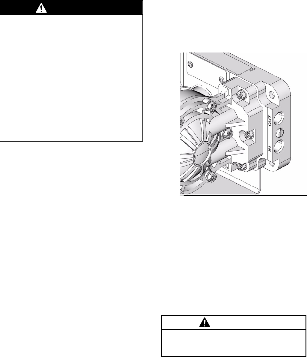
Fig. 3. On each end of the fluid manifold are a fluid IN
port and a fluid OUT port. NOTE: Make sure the fluid
OUT port on the fluid manifold is mounted up. This
will assure proper pump priming. Fluid-in and fluid-
out lines can be connected on the same end, or
opposite ends of the manifold. Plug ports that are not
used (plugs provided).
Fi
g
. 3
06179A
ti10661a
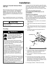
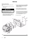
Typical Installation
The installations shown in Fig. 4 are only a guide to
help select and install a pump; they are not actual
system designs.
Typical installation includes (not supplied by Graco):
D For solenoid operation: a four-way, 5-port, 3-posi-
tion solenoid valve with 1/4-in. ports, or two 3–posi-
tion 3–way valves. Mac series 44 (4–way), or series
35 (3–way). Either way, air pressure should be
released if not cycling.
D PLC or timer. Consult your local industrial controls
distributor.
For solenoid operation, the pump must exhaust
through the solenoid. Failure to exhaust through
solenoid could cause the diaphragms to fail.
CAUTION