


7308118
Installation
NOTE: Reference numbers and letters in parentheses
in the text refer to the callouts in the figures and the
Parts Drawing.
NOTE: Contact you Graco distributor for available
Graco accessories. If you supply your own accesso-
ries, be sure they are adequately sized and pressure-
rated to meet the system’s requirements.
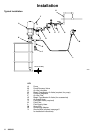
The Typical Installation shown on page 6 is only a
guide for selecting and installing system components
and accessories. Contact your Graco distributor for
assistance in designing a system to suit your particular
needs.
System Accessories
Refer to the Typical Installation on page 6.
WARNING
A bleed-type master air valve (D) and a fluid drain
valve (J) are required in your system. These acces-
sories help reduce the risk of serious injury includ-
ing fluid injection, splashing in the eyes or on the
skin, and injury from moving parts if you are adjust-
ing or repairing the pump.
The bleed-type master air valve relieves air trapped
between this valve and the pump after the air is
shut off. Trapped air can cause the pump to cycle
unexpectedly. Locate the valve close to the pump.
The fluid drain valve assists in relieving fluid pres-
sure in the displacement pump, hose, and gun.
Triggering the gun to relieve pressure may not be
sufficient.
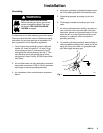
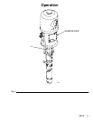
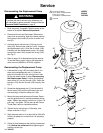
Mounting Accessories
Mount the pump (A) to suit the type of installation
planned. The pump dimensions and mounting hole
layout are shown on page 26.
The pump is supplied with a bung adapter. To mount
the pump, loosen the bung adapter screw and slide the
adapter off the pump. Screw the bung adapter secure-
ly into the bung hole on the cover of the supply drum.
Carefully lower the pump through the bung adapter
and into the drum until it rests on the bottom, then pull
it back up 1/2 in. (13 mm). Tighten the bung adapter
screw to hold the pump in this position. Open the
drum’s vent plug to prevent a vacuum from forming in
the drum.
Air and Fluid Hoses
Be sure all air and fluid hoses are properly sized and
pressure-rated for your system. Use only electrically
conductive air and fluid hoses. Fluid hoses must have
spring guards on both ends.
Connect a electrically conductive fluid hose (L) to the
fluid filter (K), if used, or directly to the pump’s fluid
outlet.
Use a electrically conductive 1/2 in. ID (minimum) air
hose (H) to supply air to the pump.
Air Line Accessories
Install the following accessories in the order shown in
the Typical Installation, using adapters as necessary.
D An air line lubricator (C) provides automatic air
motor lubrication.
D A bleed-type master air valve (D) is required in
your system to relieve air trapped between it and
the air motor when the valve is closed (see the
WARNING at left). Be sure the bleed valve is easily
accessible from the pump, and is located down-
stream from the air regulator.
D A pump runaway valve (B) senses when the
pump is running too fast and automatically shuts off
the air to the motor. A pump which runs too fast can
be seriously damaged.
D An air regulator (E) controls pump speed and
outlet pressure by adjusting the air pressure to the
pump. Locate the regulator close to the pump, but
upstream from the bleed-type master air valve.
D An air line filter (F) removes harmful dirt and
moisture from the compressed air supply.
D A second bleed-type master air valve (G) iso-
lates the air line accessories for servicing. Locate
upstream from all other air line accessories.
Fluid Line Accessories
Install the following accessories in the positions shown
in the Typical Installation, using adapters as neces-
sary:
D A fluid drain valve (J) is required in your system
to relieve fluid pressure in the hose and gun (see
the WARNING at left). Install the drain valve point-
ing down, but so the handle points up when
opened.
D A fluid filter (K) filters harmful particles from the
fluid.
D A spray gun (M) dispenses the fluid. The gun
shown in the Typical Installation is an airless
spray gun.