


16 308118
Service
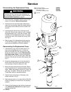
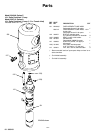
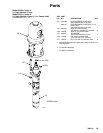
Displacement Pump Service
Reassembly
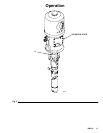
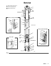
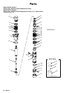
1. Lubricate the throat packings and install them in
the outlet housing (5) one at a time as follows, with
the lips of the v-packings facing down: the male
gland (4*), one UHMWPE v-packing (3*), two
PTFE v-packings (25*), one UHMWPE v-packing
(3*), and the female gland (2*). Apply thread
lubricant to the packing nut (14), and screw it
loosely into the outlet housing. See Fig. 4.
2. Lubricate the piston packings and install them on
the piston stud (27) one at a time in the following
order, with the lips of the v-packing facing up: the
shims (35; use 0–3 as required), the female gland
(31*), one UHMWPE v-packing (30*), two PTFE
v-packings (29*), one UHMWPE v-packing (30*),
the male gland (28*), and the washer (26*). See
Fig. 4.
3. Apply thread sealant and screw the piston stud
(27) onto the piston mounting stud (13). Torque to
50–70 ft-lb (68–95 NSm). Install the piston ball
(16*) on the piston seat. Slide the ball stop pin
(11*) into the desired set of holes, and secure with
the cotter pin (12*).
4. Check that the coupling nut (7), jam nut (9) and
adapter (10) are in place on the connecting rod (8).
The bottom of the adapter (10) should be flush
with the end of the rod (8); tighten the jam nut (9)
down securely to lock these parts. Apply thread
sealant to the male threads of the adapter (10).
Screw the piston mounting stud (13) onto the
connecting rod adapter (10), and torque to 50–70
ft-lb (68–95 NSm).
5. Place the flats of the displacement rod (1) in a
vise. Apply thread lubricant to the bottom threads
of the rod. Couple the connecting rod (8) to the
displacement rod with the coupling nut (7). TIghten
the nut securely.
6. Place the o-ring (6) into the outlet housing (5).
Slide the displacement rod and connecting rod
assembly up into the outlet housing (5) until the
displacement rod protrudes from the packing nut
(14).
NOTE: Before replacing the pump cylinder, note its
orientation. Failure to install correctly may result in
failure of pump or premature seal wear. Inspect the
inner diameter of both ends of the cylinder for
smoothness and size. The rougher and larger end
should mate with the outlet housing (5) upon
reassembly.
7. Apply thread lubricant to the top threads of the
cylinder (15). Slide the cylinder straight up over the
connecting rod (8) and displacement rod (1), being
careful not to scratch the cylinder by tilting it.
Screw the cylinder into the outlet housing (5).
8. Install the ball (18*), o-ring (19) and ball stop pin
(17*) in the intake valve housing (21). Apply thread
lubricant to the bottom threads of the cylinder (15).
Place the intake valve assembly in the locking ring
(20), and screw the ring onto the cylinder (15).
9. Reconnect the displacement pump to the motor as
explained on page 14.