


Repair
308391J 13
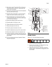
14. Align the tie rods (47) and bolts (23) and torque to
70 to 80 ft-lbs (95 to 108 N.m). Install eyelet (26)
Attach hoist to the eyelet.
15. Screw the top and bottom flare nuts on the hydraulic
tube (49), and install the tube.
16. Place the motor horizontally in a vise at the pump
adapter (42) and the bottom cylinder cap (43).
17. Apply thread sealant to the threads of the piston
(110) and install the piston, ball (103), and the seal
(107) with the lips facing up.
18. Remove the hydraulic motor from the vise.
19. Place the piston (110) flats in a vise.
20. Tighten the piston rod (44) with a wrench.
21. Remove the piston from the vise.
22. Place the pump horizontally in the vise.
23. Install the displacement pump with a strap wrench.
24. Remove the hydraulic motor from the bench vise.
25. Unplug all hydraulic connections and lines and con-
nect the hydraulic hoses. Connect the displacement
pump hoses.
26. Flush the displacement pump if possible. Relieve
the pressure (page 8)
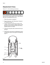
Intake Valve
Refer to FIG. 5 for the following instructions.
1. Relieve the pressure, see page 8.
2. Unscrew the valve body (112). Remove the o-ring
(105), ball (104), and retainer (113).
3. Inspect the parts for wear or damage. If the ball is
nicked, replace it. Reassemble, using grease on the
male threads.
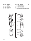
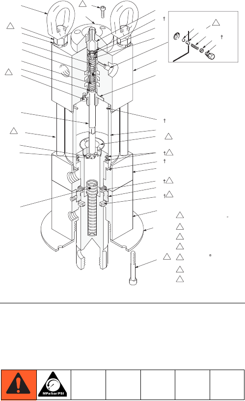
FIG. 4
26
5
22
33
18
16
41
50
12
15
12
17
42
47
25
Lips must face
up toward top of motor
Rings must be positioned
with joints opposed 180
38
31
30
7
41
Apply Loctite TL–242
thread sealant to threads
43
Torque to
70–80 ft–lb (95–108 N.m)
1
4
5
2
1
2
6
4
6
Concave surface faces ball
6
37
10
34
34 36
9
7
7
Torque to
120–130 ft–lb (163–176 N.m)
17
3
Lips must face down to-
ward bottom of pump
3
4
5
29
21
46
32
40
11
39
5
35
45
5