


Repair
12 308391J
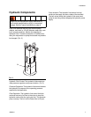
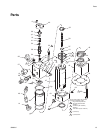
16. Remove the stop plug (39) from the upper housing
(36). Pull the upper housing about 3 inches off the
cylinder (35). Shim the housing with 3/4 in. flat stock
to keep an opening. The cylinder can stay in the
lower housing (43).
17. Hold the trip rod (33) steady with a trip rod pliers
(P/N 207579) on the rod, and remove the top hex
nut (16) from the trip rod.
18. Remove the upper housing (36). Remove the valve
spool (38) from the upper housing (36). Save the
spring collars (41), the springs (34), and the parts
remaining inside the upper housing.
19. Inspect the bore in the upper housing (36) and the
outside diameter of the valve spool (38) for wear.
Replace parts if damaged. Inspect the trip rod (33)
above the shoulder for damage. There must be no
reduction in diameter.
20. Pull the trip rod and piston rod (44) from the lower
housing (43) and cylinder (35).
21. The seals (17) must be replaced if they are leaking.
Remove seals from adapter (42).
22. Perform steps 23 and 24 if parts inspected in step
19 are damaged.
23. Place the piston rod (44) in a vise; tighten the vise
on the flats of the piston rod. Use a spanner wrench
to remove the retainer (32). Remove the trip rod (33)
from the piston rod (44).
24. Remove the trip rod nut (10) and piston stop (37). If
the piston rod is replaced, remove the compression
springs (18), and compression rings (15) to use the
new piston rod.
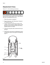
Reassembly
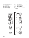
Refer to FIG. 4 for the following instructions.
1. Place the pump adapter (42) in a vise. Grease the
new seal (17) from the repair kit. Install a seal in the
pump adapter (42) with the lip facings down. Install
the rod guide (45) and install the second seal with
the lip facing up in the pump adapter. Install the bot-
tom cylinder cap (43). Ensure all fluid ports are fac-
ing the same direction.
2. Install the piston rod (44) into the pump adapter (42)
and the bottom cylinder cap (43). Lubricate the pis-
ton rings (15) and install the piston rod (44) with the
openings on the rings opposed 180°.
3. Only perform steps 4 and 5 if steps 23 and 24 of
Disassembly were performed.
4. Install the compression spring (18) inside the piston
rod. Install the trip rod nut (10) and piston stop (37)
on the trip rod (33).
5. Install the trip rod (33) in the piston rod (44). Apply
thread sealant to the retainer (32). With the piston
flat in a vise, tighten the retainer until it is flush or
below the piston surface. This is important to pre-
vent the retainer from backing out during operation
and damaging the motor.
6. Install the o-ring (12) on cylinder (35). Install the cyl-
inder over the piston and rings.
7. Install the upper housing (36). Install a 3/4 inch flat
stock shim between the upper housing and the cyl-
inder. Install the trip rod guide (41), the spring (34),
valve spool (38), and the remaining parts from the
inside of the upper housing. See Parts Drawing,
page 15,
8. Holding the trip rod (33) steady with a trip rod pliers
on the rod, and install the top hex nut (16) on the trip
rod.
9. Replace the o-ring (11) on the stop plug (39). Install
the stop plug in the upper housing (36).
10. Install tie rods (47) and bolts (23); hand tighten.
11. Install the two lock nuts (5) and washers (6).
12. Apply thread sealant to the socket screws (9). Install
the end cap (40) with the socket screws.
13. Install one detent assembly; retaining plug (31),
spring (21), gasket (29), ball guide (30), and ball (7).
Repeat for the other detent assembly.
NOTICE
With the bolts removed, the assembly may separate
at the joints between the cylinder (35) and the upper
housing (36) and bottom cylinder cap (43),
NOTICE
To avoid damaging the internal parts, install detent
parts (31, 21, 29, 30, and 7) after install the end cap
(40).