


6
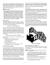
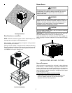
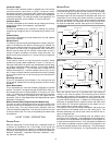
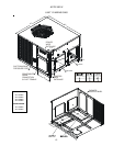
Remove these covers
for horizontal duct
applications
Remove these panels
for downflow duct
applications
Supply
Return
Duct Cover Installation
Down Discharge Applications
Cut insulation around bottom openings and remove panels from
the bottom of the unit, saving the screws holding the panels in
place.
NOTE: Single phase models require installation of horizontal duct
kit #20464501PDGK (medium chassis) and #20464502PDGK
(large chassis).
DUCT WORK
Duct systems and register sizes must be properly designed for
the C.F.M. and external static pressure rating of the unit. Duct work
should be designed in accordance with the recommended methods
of Air Conditioning Contractors of America Manual D (Residential)
or Manual Q (Commercial). All ductwork exposed to the outdoors
must include a weatherproof barrier and adequate insulation.
A duct system should be installed in accordance with Standards of
the National Board of Fire Underwriters for the Installation of Air
Conditioning, Warm Air Heating and Ventilating Systems. Pamphlets
No. 90A and 90B.
The supply duct from the unit through a wall may be installed
without clearance. However, minimum unit clearances as shown
in the appendix must be maintained. The supply duct should be
provided with an access panel large enough to inspect the air
chamber downstream of the heat exchanger. A cover should be
tightly attached to prevent air leaks.
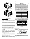
For duct flange dimensions on the unit refer to the Unit Dimension
illustration in the appendix.
For down-discharge applications, the ductwork should be attached
to the roof curb prior to installing the unit. Duct work dimensions are
shown in the roof curb installation manual.
If desired, supply and return duct connections to the unit may be
made with flexible connections to reduce possible unit operating
sound transmission.
FILTERS
CAUTION
T
O PREVENT PROPERTY DAMAGE DUE TO FIRE AND LOSS OF
EQUIPMENT EFFICIENCY OR EQUIPMENT DAMAGE DUE TO DUST AND LINT
BUILD UP ON INTERNAL PARTS, NEVER OPERATE UNIT WITHOUT AN AIR
FILTER INSTALLED IN THE RETURN AIR SYSTEM.
Filters are not provided with unit and must be supplied and exter-
nally installed in the return duct system by the installer. An optional
factory approved internal filter rack may also be used. A field-in-
stalled filter grille is recommended for easy and convenient ac-
cess to the filters for periodic inspection and cleaning. When
installing filters, ensure the air flow arrows on the filter are pointing
toward the circulator blower.
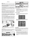
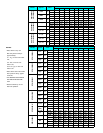
Refer to the unit filter size chart below for filter size information.
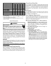
NOMINAL SIZE (INCHES) NOMINAL AREA (SQ. FT.)
10x20 1.4
14x20 1.9
14x25 2.4
15x20 2.1
16x20 2.2
16x25 2.8
20x20 2.8
20x25 3.5
25x25 4.3
MINIMUM FILTER SIZE
NOTE: Filters must have adequate face area for the rated quantity
of the unit. See the air delivery table below for recommended filter
size. Size the filters in accordance with their manufacturer recom-
mendations. Throwaway filters must be sized for a maximum face
velocity of 300 feet per minute.
500 1000 1500 2000 2500 3000 3500
7
6
5
4
3
2
D
I
S
P
O
S
A
B
L
E
F
I
L
T
E
R
P
E
R
M
A
N
E
N
T
F
I
L
T
E
R
Airflow - SCFM
N
o
m
i
n
a
l
F
i
l
t
e
r
A
r
e
a
S
q
u
a
r
e
F
e
e
t
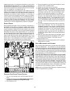
PIPING
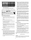
CONDENSATE D RAIN
The condensate drain connection of the evaporator is a half cou-
pling of ¾” N.P.T. A trap must be provided to have Proper conden-
sate drainage.
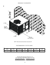
2" Minimum
3" Minimum
A Positive Liquid Seal
Is Required
Flexible
Tubing-Hose
Or Pipe
Drain
Connection
Unit
Install condensate drain trap as shown. Use ¾ “ drain connection
size or larger. Do not operate without trap. Unit must be level or
slightly inclined toward drain.