


2
WARNING
I
NSTALLATION
AND
REPAIR
OF
THIS
UNIT
SHOULD
BE
PERFORMED
ONLY
BY
INDIVIDUALS
MEETING
THE
REQUIREMENTS
OF
AN
“E
NTRY
L
EVEL
T
ECHNICIAN
”
AS
SPECIFIED
BY
THE
A
IR
-C
ONDITIONING
, H
EATING
,
AND
R
EFRIGERATION
I
NSTITUTE
(AHRI). A
TTEMPTING
TO
INSTALL
OR
REPAIR
THIS
UNIT
WITHOUT
SUCH
BACKGROUND
MAY
RESULT
IN
PRODUCT
DAMAGE
,
PERSONAL
INJURY
OR
DEATH
.
(
AT
A
MINIMUM
)
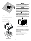
TO THE INSTALLER
Carefully read all instructions for the installation prior to installing
unit. Make sure each step or procedure is understood and any
special considerations are taken into account before starting in-
stallation. Assemble all tools, hardware and supplies needed to
complete the installation. Some items may need to be purchased
locally. After deciding where to install unit, closely look the location
over - both the inside and outside of home. Note any potential
obstacles or problems that might be encountered as noted in this
manual. Choose a more suitable location if necessary.
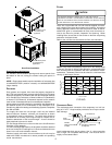
IMPORTANT NOTE: If a crankcase heater is used, the unit
should be energized 24 hours prior to compressor start up to
ensure crankcase heater has sufficiently warmed the compres-
sor. Compressor damage may occur if this step is not fol-
lowed.
IMPORTANT NOTE TO THE OWNER REGARDING PRODUCT
WARRANTY
Your warranty certificate is supplied as a separate document
with the unit installed by your contractor. Read the limited
warranty certificate carefully to determine what is and is not
covered and keep the warranty certificate in a safe place. If
you are unable to locate the warranty certificate please contact
your installing contractor or contact customer service (877-
254-4729) to obtain a copy.
IMPORTANT: To receive the 10-year Parts Limited Warranty,
online registration must be completed within 60 days of
installation. Online registration is not required in California or
Quebec.
To register your Goodman brand unit, go to
www.goodmanmfg.com. Click on the word “Warranty” located
on the left side of the home page. Next, click on the word
INDEX
TO THE INSTALLER ................................................2
T
O THE OWNER ...................................................2
SHIPPING INSPECTION..........................................3
REPLACEMENT PARTS ..........................................3
O
RDERING PARTS ..................................................3
SAFETY INSTRUCTIONS........................................3
CODES AND REGULATIONS ..................................3
EPA R
EGULATIONS ................................................4
N
ATIONAL CODES ..................................................4
MAJOR COMPONENTS ..........................................4
PRE-INSTALLATION CHECKS................................4
C
LEARANCES AND ACCESSIBILITY ..............................4
U
NIT LOCATION ......................................................4
G
ROUND LEVEL PRE-INSTALLATION DETAILS ...............4
R
OOF TOP PRE-INSTALLATION DETAILS .....................4
R
OOF CURB INSTALLATIONS ONLY ............................5
R
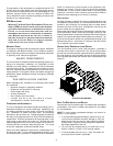
IGGING DETAILS ..................................................5
CIRCULATING AIR AND FILTERS...........................5
A
IRFLOW CONVERSION ...........................................5
D
UCT WORK ..........................................................6
F
ILTERS ...............................................................6
PIPING.......................................................................6
C
ONDENSATE DRAIN ...............................................6
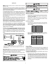
WIRING......................................................................7
H
IGH VOLTAGE WIRING ...........................................7
L
OW VOLTAGE WIRING............................................7
I
NTERNAL WIRING...................................................7
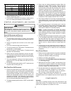
STARTUP, ADJUSTMENTS, AND CHECKS ...........8
S
TART-UP PROCEDURE AND CHECKLIST .....................8
H
EAT PUMP START-UP PROCEDURE ..........................8
F
INAL SYSTEM CHECKS..........................................8
COMPONENTS ........................................................8
C
ONTACTOR ..........................................................8
C
RANKCASE HEATER ..............................................9
C
ONDENSER MOTOR ..............................................9
C
OMPRESSOR .......................................................9
C
ONTACTOR RELAY ................................................9
D
EFROST CONTROL ................................................9
O
UTDOOR THERMOSTAT ..........................................9
R
EVERSING VALVE COIL .........................................9
I
NDOOR BLOWER MOTOR ........................................9
B
LOWER INTERLOCK RELAY .....................................9
HEAT PUMP OPERATION .......................................9
C
OOLING CYCLE ...................................................9
H
EATING CYCLE ....................................................9
D
EFROST CONTROL ..............................................10
S
UGGESTED FIELD TESTING/TROUBLE SHOOTING ......10
A
IRFLOW MEASUREMENT AND ADJUSTMENT ...............10
S
PEED TAP ADJUSTMENTS
FOR INDOOR BLOWER MOTOR ...........................12
R
EFRIGERANT CHARGE CHECKS .............................12
ELECTRICAL ADJUSTMENTS..............................12
MAINTENANCE ......................................................13
S
ERVICE ............................................................13
I
NADEQUATE AIR VOLUME THROUGH INDOOR COIL .....13
O
UTSIDE AIR INTO RETURN DUCT ..........................13
U
NDERCHARGE ....................................................13
P
OOR “TERMINATING” SENSOR CONTACT ................13
M
ALFUNCTIONING REVERSING VALVE -
T
HIS MAY BE DUE TO: .......................................13
TROUBLESHOOTING CHART .............................14
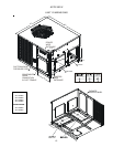
APPENDIX...............................................................15
UNIT DIMENSIONS................................................15
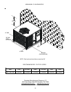
MINIMUM CLEARANCES ......................................16
RECOMMENDED FILTER SIZES ..........................16