


12
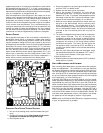
SPEED TAP ADJUSTMENTS FOR INDOOR BLOWER MOTOR
PSC Motor
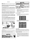
Adjust the CFM by changing the speed tap of the indoor blower
motor at the EBTDR “COM” connection with one of the speed taps
on “M1” or “M2”. (Black-High Speed, Blue-Medium Speed, Red-
Low Speed.)
X-13 Motor
Adjust the CFM by changing the 24V low voltage lead at the speed
terminal block on the motor. (T1-Low Speed, T2 and T3-Medium
Speed, T4 and T5-High Speed).
REFRIGERANT CHARGE C HECKS
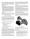
After completing airflow measurements and adjustments, the unit’s
refrigerant charge must be checked. The unit is factory charged
based on 400 CFM per ton at minimum ESP per AHRI test condi-
tions (generally between .15 - .25 ESP). When air quantity or ESP
is differs from this, charge must be readjusted to the proper amount.
All package units are charged to the superheat method at the
compressor suction line (these are fixed orifice devices).
For charging in the warmer months, 8 +/-3
º
F superheat at the com-
pressor is required at conditions: 95
º
F outdoor ambient (dry bulb
temperature), 80
º
F dry bulb / 67
º
F wet bulb indoor ambient, ap-
proximately 50% humidity. This superheat varies when conditions
vary from the conditions described.
A superheat charge chart is available for other operating condi-
tions. Use it to provide the correct superheat at the conditions the
unit is being charged at.
After superheat is adjusted it is recommended to check unit sub-
cooling at the condenser coil liquid line out. In most operating
conditions 10 - 15ºF of sub-cooling is adequate.
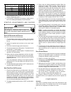
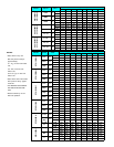
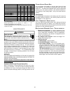
SUPERHEAT = SUCTION LINE TEMP - SAT. SUCTION TEMP
Suction
Pressure
Saturated Suction
Tem
p
erature °F
PSIG R-410A
50 1
52 3
54 4
56 6
58 7
60 8
62 10
64 11
66 13
68 14
70 15
72 16
71 17
76 19
78 20
80 21
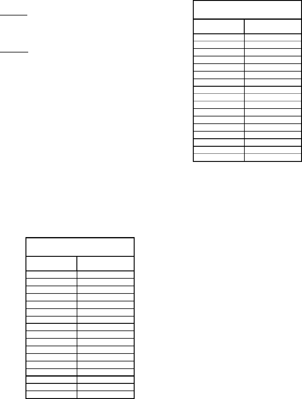
SATURATED SUCTION PRESSURE
TEMPERATURE CHART
SUBCOOLING = SAT. LIQUID TEMP. - LIQUID LINE TEMP.
Liquid
Pressure
Saturated Liquid
Tem
p
erature °F
PSIG R-410A
200 70
210 73
220 76
225 78
235 80
245 83
255 85
265 88
275 90
285 92
295 95
305 97
325 101
355 108
375 112
405 118
SATURATED LIQUID PRESSURE
TEMPERATURE CHART
SYSTEM SUPERHEAT
SUPERHEAT CAN BE DETERMINED AS FOLLOWS:
1. Read suction pressure. Determine Saturated Suction
Temperature from tables or pressure gauge saturated
temperature scale (R-410A).
2. Read suction line temperature.
3. Use the following formula:
SUPERHEAT = SUCTION LINE TEMP - SAT. SUCTION TEMP
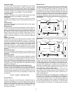
ELECTRICAL ADJUSTMENTS
This series of electric cooling and, heat pump package equipment
is designed to accept a field installed electric heat kit. The unit is
equipped to easily install the HKR Series Electric Heat Kit. Full In-
stallation Instructions are included in this kit. Please use this docu-
ment for guidance in field equipping the package unit with electric
heat.
Choose the heat kit that fits the application for the specific installa-
tion. Permanently mark the unit’s nameplate with the model being
installed. High and low voltage connections are detailed in the heat
kit instructions.
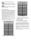
Indoor Blower motor speed tap selection may need to be modified
to accommodate normal continuous operation to prevent a nui-
sance trip. See following table.