


4
The information on the rating plate is in compliance with the FTC
& DOE rating for single phase units. The three phase units in
this series are not covered under the DOE certified program. The
efficiency ratings of these units are a product of thermal effi-
ciency determined under continuous operating conditions inde-
pendent of any installed system.
EPA REGULATIONS
IMPORTANT: THE UNITED STATES ENVIRONMENTAL PROTECTION
AGENCY (EPA) HAS ISSUED VARIOUS REGULATIONS REGARDING
THE
INTRODUCTION AND DISPOSAL OF REFRIGERANTS IN THIS UNIT.
FAILURE TO FOLLOW THESE REGULATIONS MAY HARM THE
ENVIRONMENT
AND CAN LEAD TO THE IMPOSITION OF SUBSTANTIAL
FINES
. BECAUSE REGULATIONS MAY VARY DUE TO PASSAGE OF
NEW
LAWS, WE SUGGEST A CERTIFIED TECHNICIAN PERFORM ANY
WORK
DONE ON THIS UNIT. SHOULD YOU HAVE ANY QUESTIONS
PLEASE
CONTACT THE LOCAL OFFICE OF THE EPA.
NATIONAL CODES
This product is designed and manufactured to permit installation
in accordance with National Codes. It is the installer’s responsi-
bility to install the product in accordance with National Codes and/
or prevailing local codes and regulations.
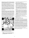
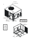
MAJOR COMPONENTS
The unit includes a hermetically sealed refrigerating system (con-
sisting of a compressor, condenser coil, evaporator coil with
flowrator), an indoor blower, a condenser fan and all necessary
internal electrical wiring. The heat pump also includes a revers-
ing valve, solenoid, defrost thermostat and control and loss of
charge protection. The system is factory-evacuated, charged and
performance tested. Refrigerant amount and type are indicated
on rating plate.
PRE-INSTALLATION CHECKS
Before attempting any installation, the following points should
be considered:
• Structural strength of supporting members
• Clearances and provision for servicing
• Power supply and wiring
• Air duct connections
• Drain facilities and connections
• Location may be on any four sides of a home,
manufactured or modular, to minimize noise
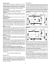
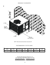
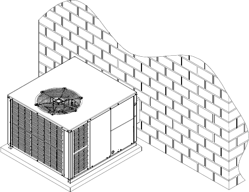
CLEARANCES AND A CCESSIBILITY
The unit is designed to be located outside the building with un-
obstructed condenser air inlet and discharge. Additionally, the
unit must be situated to permit access for service and installa-
tion. Condenser air enters from three sides. Air discharges
upward from the top of the unit. Refrigerant gauge connections
are made on the right side of the unit as you face the compressor
compartment. Electrical connections can be made either on the
right, bottom or duct panel side of the unit. The best and most
common application is for the unit to be located 10” from wall (4”
minimum) with the connection side facing the wall. This “close
to the wall” application minimizes exposed wiring.
Close to the wall application assures free, unobstructed air to
the other two sides. In more confined application spaces, such
as corners provide a minimum 10” clearance on all air inlet sides.
Allow 18” minimum for service access to the compressor com-
partment and controls. The top of the unit should be completely
unobstructed. If units are to be located under an overhang, there
should be a minimum of 36” clearance and provisions made to
deflect the warm discharge air out from the overhang.
UNIT LOCATION
Consider the affect of outdoor fan noise on conditioned space and
any adjacent occupied space. It is recommended that the unit be
placed so that condenser air discharge does not blow toward
windows less than 25 feet away. Consideration should also be
given to shade and unit appearance.
Heat pumps require special location consideration in areas of heavy
snow accumulation and/or areas with prolonged continuous sub-
freezing temperatures. Heat pump unit bases have holes under the
outdoor coil to permit drainage of defrost water accumulation. The
unit must be situated to permit free unobstructed drainage of the
defrost water and ice. A minimum 2" clearance under the outdoor
coil is required in the milder climates.
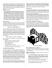
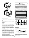
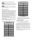
GROUND LEVEL PRE-INSTALLATION DETAILS
The unit should be set on a solid, level foundation - preferably a
concrete slab at least 4 inches thick. The slab should be above
ground level and surrounded by a graveled area for good drainage.
Any slab used as a unit’s foundation should not adjoin the building
as it is possible that sound and vibration may be transmitted to the
structure.
Ground Level Installation
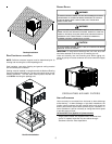
ROOF TOP PRE-INSTALLATION DETAILS
Ensure that the roof is weather tight and allows proper drainage of
condensation. Use steel or treated wood beams as unit support
for load distribution.
NOTE: To ensure proper condensate drainage, unit must be in-
stalled in a level position.
• To avoid possible property damage or personal injury, the
roof must have sufficient structural strength to carry the
weight of the unit(s) and snow or water loads as required
by local codes. Consult a structural engineer to determine
the weight capabilities of the roof.
• The unit may be installed directly on wood floors or on
Class A, Class B, or Class C roof covering material.
• To avoid possible personal injury, a safe, flat surface for
service personnel should be provided.