


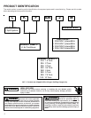
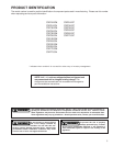
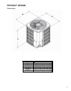

PRODUCT DESIGN
4
CKF 50 Hz models are available in 2 through 6 ton sizes.
They are designed for 220/240 to 380 volt single phase appli-
cations.
The condenser air is pulled through the condenser coil by a
direct drive propeller fan. This condenser air is then dis-
charged out of the top of the cabinet.
These units are designed for free air discharge, so no addi-
tional resistance like duct work shall be attached.
The suction and liquid line connections on present models
are of the sweat type for field piping with refrigerant type cop-
per. Back seating valves are factory installed to accept the
field run copper. The total refrigerant charge for a normal in-
stallation is factory installed in the condensing unit. CKF units
are charged for the matching evaporator coil and a 15 foot [5 m]
refrigerant line set.
Systems should be properly sized by heat gain and loss
calculations made according to methods of the Air Condi-
tioning Contractors Association (ACCA) or equivalent. It is
the contractors responsibility to ensure the system has ad-
equate capacity to heat or cool the conditioned space.
CKF condensing units use a mix of Copeland Reciprocating
®
and Copeland Compliant
®
Scroll compressors. There are a
number of design characteristics which are different from the
scroll compared to the traditional reciprocating compressor.
Due to their design Scroll compressors are inherently more
tolerant of liquid refrigerant.
NOTE: Even though the compressor section of a Scroll com-
pressor is more tolerant of liquid refrigerant, continued flood-
back or flooded start conditions may wash oil from the bear-
ing surfaces causing premature bearing failure.
Copeland Compliant
®
Scroll compressors use white oil which
is compatible with 3GS. 3GS oil may be used if additional oil
is required.
The CKF condensers use new generation scroll compres-
sors. These compressors have an internal equalization mecha-
nism and an anti-counter rotation device which allow the scrolls
to equalize in approximately ½ second at shut down.
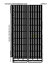
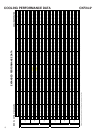
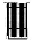
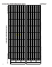
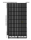
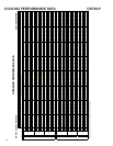
Operating pressures, amp draws and minimum circuit am-
pacity may differ from standard reciprocating compressors.
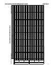
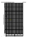
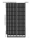
This information may be found in the "Cooling Performance
Data" section and should be reviewed prior to installation of
the condenser.
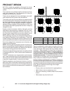
OK!
OK!
AA AAA
A
CC
C
C
OK!
OK!
OK!
OK!
NOT
RECOMMENDED
AA
AA
AA
AA
AA
B B B
B
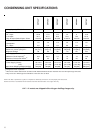
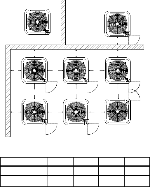
Model Type A B C AA
Residential
10 [25] 10 [25] 18 [46] 20 [51]
Light Commercial
12 [30] 12 [30] 18 [46] 24 [61]
Measurements in inches. [ ] Designates metric equivalents.
Special consideration must be given to location of the con-
densing unit(s) in regard to structures, obstructions, other
units, and any/all other factors that may interfere with air
circulation. Where possible, the top of the unit should be
completely unobstructed; however, if vertical conditions re-
quire placement beneath an obstruction there should be a
minimum of 60 in. [152 cm] between the top of the unit
and the obstruction(s). The specified dimensions meet re-
quirements for air circulation only. Consult all appropriate regu-
latory codes prior to determining final clearances.
Another important consideration in selecting a location for
the unit(s) is the angle to obstructions. Either side adjacent
the valves can be placed toward the structure provided the
side away from the structure maintains minimum service clear-
ance. Corner installations are strongly discouraged.
DO NOT locate the unit:
– Directly under a vent termination for a gas appliance.
– Within 3 feet [1 m] of a clothes dryer vent.
– Where the refreezing of defrost water would create a
hazard.
– Where water may rise into the unit.
CKF**-*P* models are shipped with a nitrogen holding charge only.