


—15—
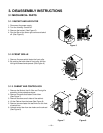
1. When replacing the refrigeration cycle, be sure to
discharge the refrigerant system by using a
refrigerant recovery system.
2. After discharging the unit completely, remove the
desired component, and unbrace the pinch-off
tubes.
3. Solder service valves into the pinch-off tube ports,
leaving the valves open.
4. Solder the pinch-off tubes with service valves.
5. After doing the above procedures, the valve must
be closed and left in place on the system for any
subsequent procedures.
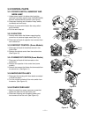
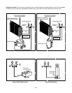
6. Evacuate as follows.
1) Connect the vacuum pump, as illustrated in
Figure 22A.
2) Start the vacuum pump, slowly open manifold
valves A and B with two full turns
counterclockwise and leave the valves closed.
The vacuum pump is now pulling through valves
A and B up to valve C by means of the manifold
and entire system.
3) Operate the vacuum pump for 20 to 30 minutes,
until 600 microns of vacuum are obtained. Close
valves A and B, and observe vacuum gauge for
a few minutes. A rise in pressure would
indicate a possible leak or moisture remaining in
the system. With valves A and B closed, stop
the vacuum pump.
4) Remove the hose from the vacuum pump and
place it on the charging cylinder. See Figure 22B.
Open valve C.
Discharge the line at the manifold connection.
5) The system is now ready for final charging.
7. Recharge as follows :
1) Refrigeration cycle systems are charged from the
High-side. If the total charge cannot be put
in the High-side, the balance will be put in the
suction line through the access valve which you
installed as the system was opened.
2) Connect the charging cylinder as shown in Figure
22B.
With valve C open, discharge the hose at the
manifold connection.
3) Open valve A and allow the proper charge to
enter the system. Valve B is still closed.
4) If more charge is required, the high-side will not
take it. Close valve A.
5) With the unit running, open valve B and add the
balance of the charge.
a. Do not add the liquid refrigerant to the Low-
side.
b. Watch the Low-side gauge; allow pressure to
rise to 30 lbs.
c. Turn off valve B and allow pressure to drop.
d. Repeat steps B and C until the balance of the
charge is in the system.
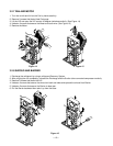
6) When satisfied the unit is operating correctly,
use the pinch-off tool with the unit still running
and clamp on to the pinch-off tube. Using a tube
cutter, cut the pinch-off tube about 2 inches from
the pinch-off tool. Use sil-fos solder and solder
pinch-off tube closed. Turn off the unit, allow it to
set for a while, and then test the leakage of the
pinch-off connection.
If high vacuum equipment is used, just crack
valves A and B for a few minutes, then open
slowly with the two full turns counterclockwise.
This will keep oil from foaming and being drawn
into the vacuum pump.
CAUTION
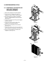
3.4 HOW TO REPLACE THE REFRIGERATION SYSTEM
NOTE:
THE REFRIGERANT R134a IS
USED SOME MODELS.
CHECK THE SPECIFICATION
LABEL ON THE CABINET.
When discharging refrigerant R134a, purging instrument
should be used only for R134a, without mixing that of
refrigerant R22.
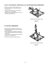
When checking the leakage of refrigerant R134a,
leakage test tool should be used only for R134a.
The pump for discharging should be high efficiency.
Final discharging value must be managed below 0.5 Torr.
Maximum water should be less than quantity 150mg in
the cycle-all tubes and H/E assembly-system.
If water quantity is over 150mg, it causes acid or
corrosion in the cycle system and the capillary tube to be
clogged by water and harmful materials.
The model charged the refrigerant R134a should be
used dryer to prevent water from overflowing.