


8
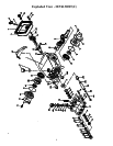
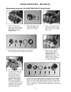
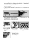
Gear End Disassembly
Note: Make certain that the plungers (29B) have been removed before starting the following sequence.
12. Make sure the oil is drained from the pump before removing the crankcase cover (#4). Remove all screws (#10). Inspect the
crankcase cover o-ring (#5) for damage and replace it as necessary.
13. Remove the connecting rod screws and washers (#'s 24A and 24B) with a 6mm allen wrench. Remove the back halves of each
connecting rod (#24) . Push the connecting rods down as far as possible into the crankcase (#1) housing. Note that the
connecting rod halves are numbered (or colored) and that the numbers (or colors) must be matched for reassembly.
14. Remove the crankshaft bearing cover screws (#17) with a 13mm wrench. Remove the key (#23) from the crankshaft (#22).
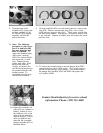
15. Remove the bearing cover (#14) and any shims (#20A) if any. Remember to replace shims on the same side of the crankcase
(#1) during the reassembly.
16. Steady the pump gear end and, using a rubber mallet, tap the crankshaft (#22) from one side. The far side bearing race will be
removed and the near side race will remain in the crankcase. The roller bearings (#20) will remain on the crankshaft. When
both ends are free, the crankshaft can be removed by hand.
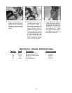
17. To remove the remaining bearing race, place a dowel against the inside edge of the race and tap it out with a rubber mallet.
This is done only if the race wear surface has been damage.
18. Inspect the bearing race removed with the crankshaft (#22) and replace if wear surface is damaged.
19. Note: The following procedure is only necessary if the inspection shows evidence of heavy wear. Inspect the crankshaft
(#22) and bearings (#20) for wear. To remove the roller bearings from the crankshaft, use a three inch push puller with a pulley
attachment. To remount the bearings, tap the bearings down the well-lubricated crankshaft with the Giant Bearing Tool. Be
sure that the bearing is firmly seated.
20. Remove the connecting rod (#24) with the attached crosshead/plunger assembly (#25) from the crankcase (#1) by pulling it
straight out. The oil seals (#31) may now be removed by tapping them out through the front of the crankcase. Be careful not
to damage the snap ring.
21. Inspect the surfaces of the crosshead/plunger assembly (#25) and connecting rods (#24) for heavy scoring or galling due to
poor lubrication. Check for play at the joint between connecting rod crosshead/plunger assembly.
22. To remove the crosshead pin (#28) from the crosshead/plunger assembly (#25), the assembly should be positioned in such
a manner to prevent damage to the crosshead when driving the pin out. The crosshead pin can be driven out by tapping on
the tapered side of the pin
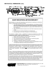
Reassembly sequence
Note: Always take time to lubricate all metal and nonmetal parts with a light film of oil before reassembly. This step will help
ensure a proper fit, at the same time it will protect the pump nonmetal parts (elastomers) from cutting and scoring.
23. Take the crosshead/plunger rod assembly and insert the connecting rod (#24) into the crosshead/plunger assembly (#25).
Drive the tapered end of the crosshead pin (#28) into the beveled side of the crosshead and through the connecting rod
completing the assembly.
Note: The crosshead pin should not extend beyond either side of the crosshead in order to prevent damage to the crosshead
bore of the crankcase.
24. Inspect the crankcase crosshead guides for any possible damage.
25. Replace the connecting rod (#24), crosshead/plunger rod assembly (#25) into the crankcase (#1).
26. If removed previously, replace the far side bearing race into the crankcase. Tap with a rubber mallet until the edges are flush
with the crankcase surface.
27. Remove the old crankshaft seal (#15) from the bearing cover (#14). Lubricate the edges of the new seal and install using the
standard Giant Bearing Tool. Remove the bearing tool and tap around the perimeter of the seal with a rubber mallet to firmly
seat the seal. Position the far bearing cover on the crankcase (#1) and insert the cover bolts (#17). Tighten the cover evenly
to the crankcase, setting the bearing into position. Torque the cover bolts to 125 inch-pounds.
28. Insert the crankshaft (#22) with the mounted bearings (#20) through the near side of the crankcase (#1). Make certain that
the numbers (or colors) or the crankshaft correspond to the numbers (or colors) on the connecting rods (#24). Reinstall the
near side bearing race by inserting it into the crankcase. Supporting the crankshaft with one hand, tap the race with a rubber
mallet until the edge is flush with the crankcase.
NOTE: Contact Giant Industries for Service School Information. Phone: (419)-531-4600