


2
INSTALLATION INSTRUCTIONS
Installation of the Giant Industries, Inc., pump
is not a complicated procedure, but there are
some basic steps common to all pumps. The
following information is to be considered as a
general outline for installation. If you have
unique requirements, please contact Giant
Industries, Inc. or your local distributor for
assistance.
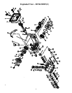
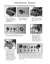
The MP4130HT has been especially constructed for
pumping hot water e.g. steam boiler storage. The plunger
seals (40) on the water side are made out of a high
temperature-resistant material. Rinsing chambers behind
the high pressure seals through which cold water can flow
thus increasing the life of the seals are available upon
request (MP4130HTC). The cold water connections (59)
are suited to the Ermeto-pipe 6mm dia. The operator can
use hose nipples instead if he wishes. There are 1/8"
threads in the seal sleeve for this purpose.
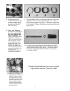
The cold water (50
o
F - 86
o
F) can be guided into the pump
from either side and flows out on the opposite side e.g.
into a drain. The cold water flow rate should be at least
0.13 GPM and must be put into use as soon as the pump is
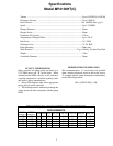
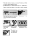
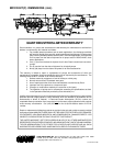
1. Prior to initial operation, add oil to the crank-
case so that oil level is between the two lines on
the oil dipstick. DO NOT OVERFILL.
Use SAE 85W - 140 Industrial Gear Oil.
Crankcase oil should be changed after the
first 50 hours of operation, then at regular
intervals of 500 hours or less depending on
operating conditions.
2. Pump operation must not exceed rated
pressure, volume, or RPM. A pressure relief
device must be installed in the discharge of the
system.
3. Acids, alkalines, or abrasive fluids cannot be
pumped unless approval in writing is obtained
before operation from Giant Industries, Inc.
4. Run the pump dry approximately 10 seconds
to drain the water before exposure to freezing
temperatures.
IMPORTANT OPERATING CONDITIONS
Failure to comply with any of these conditions invalidates the warranty.
Finally, remember that high pressure operation in a pump system has many advantages. But, if it is used carelessly
and without regard to its potential hazard, it can cause serious injury.
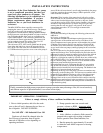
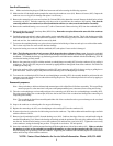
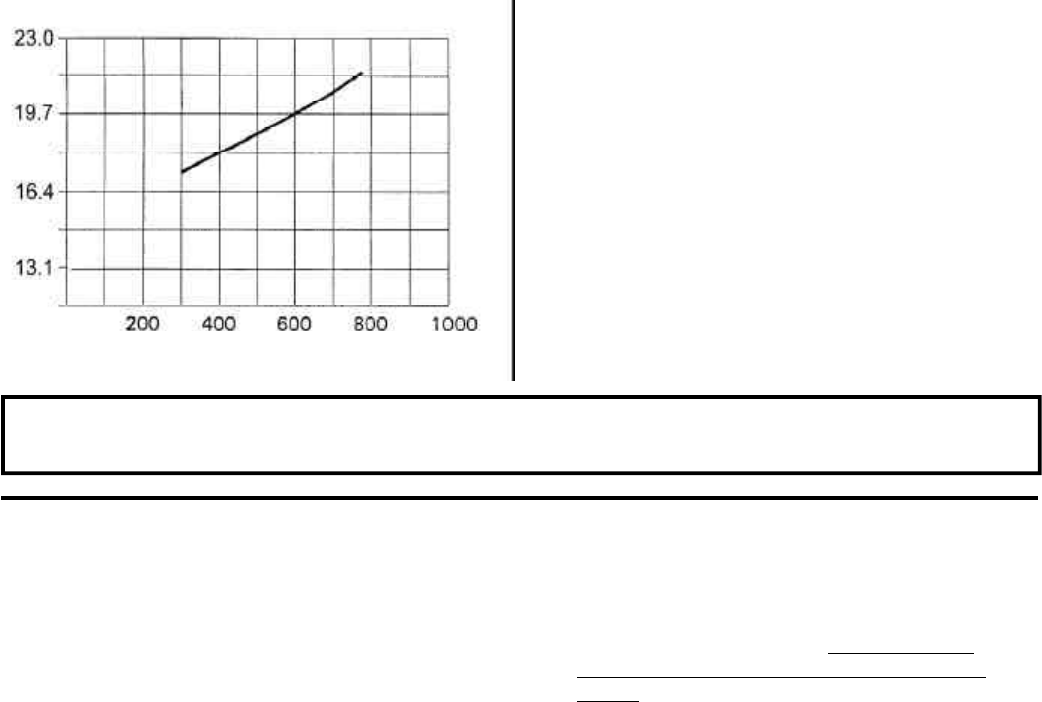
NPSHR (FT-HEAD)
RPM
started. If the cold water doesn’t start flowing immediately the pump
is put into operation, the ceramic plunger (29B) in particular, could
crack under the cold shock.
Important! If the location of the pump doesn’t allow for cooling,
on no account are the connections to be closed up because this is
where water from the high pressure seals has to drip out. In this
case, the holes can be used to fill the rinsing chambers with grease
suitable for high temperatures, by means of a grease gun, thus
assuring that the seals are always well greased. In the case of
water temperautre above 32
0
F, we strongly recommend the
cold-water rinse.
Plant Lay-Out
For perfect functioning of the pump, the following points must be
adhered to.
a) Pressure in Suction Side
The stipulated NPSHR is the minimum required pressure above
vapour pressure of the medium and is never to fall short of this
figure.Temperature and vapour pressure of the medium, the geodeti-
cal height of the location, the flow rate and loss of friction in the
suction line, must all be taken into consideration. It may be neces-
sary to install a booster pump (centrifugal pump) in the suction line.
b) Pulsation
Due to its construction, the plunger pump creates pulsation in the
suction and discharge lines. Suction pulsation in particular must be
dampened in order to prevent resonance in the suction line which in
turn, causes cavitation. Therefore, the pump is never to be con-
nected by a rigid pipe but rather by a flexible hose (not reinforced by
steel), and if possible 1.5 to 2 times wider than the suction connec-
tion. If a booster pump is used, the hose is to be attached between
the booster pump and the high pressure pump.
If several pumps are used, each pump must have its own suction
line. If this can’t be done, a suction air chamber or a suction flow
stabilizer must be installed in front of each pump. The bladder in the
stabilizer is to be pretensioned on location.
Depending on the lay-out of the plant, a pressure accumulator may
be necessary on the discharge side. This pressure accumulator must
be installed right behind the discharge outlet of the high pressure
pu We recommend the use of only one pressure accumulator in
discharge line in order to avoid irritation which could be caused by
the different pre-tension levels in the accumulators. Gas-tension in
both the suction flow stabilizer and in the pressure accumulator are
to be checked regularly.