


Z Series RO System by GE Osmonics
LOW FLOAT 2
BLACK
24 VAC HOT (BLK)
COMMON (RED)
RO CONTROLLER TERMINAL BLOCK
8
CONNECTIONS
3
1
2
4
5
6
7
TB−1
TB−4
10
9
TB−2
4
3
1
2
5
10
8
7
6
9
TB−3
CONTROLLER
CHASSIS
3
8
10
9
7
6
5
4
2
1
8
10
9
7
6
3
4
5
2
1
2
PRE−TREATMENT
INTERLOCK
LOW LOW FLOAT 2
LOW LOW FLOAT 1
BLACK
RED
TANK
1
STORAGE
5
6
COMMON (WHT)
S1−4 (BLK)
GROUND (GREEN)
S1−2 (RED)
GROUND (GREEN)
8
BLUE
13
BLK/WHT
BLACK
RED
15
14
RED/WHT
WHT/BLK
WHITE
BLACK
12
11
10
9
3
ORANGE
RED/BLK
GRN/BLK
BLU/BLK
OR/BLK
7
6
4
5
RED
2
1
RED
BLACK
RO STATUS MONITOR
PRD DIVERT
2
3
2
1
CHEM FEED
TR2−5
HIGH FLOAT 1
HIGH FLOAT 2
LOW FLOAT 1
BLACK
RED
4
2
3
RED
1
TR2−8
OVER TEMP ALARM
RO CONTROLLER TIMER
1238339b – 16Oct03 6 - 20 Drawings
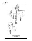
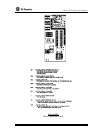
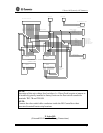
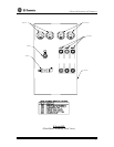
NOTE:
Operation of this unit without level switches (i.e. Direct Feed) requires a jumper to
be installed (typically installed at factory) between the float switch connection
terminals TB3-7B and TB3-8B.
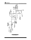
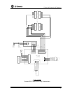
NOTE:
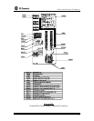
Connect the color-coded cable conductors inside the RO Controller to their
associated terminal barrier strip locations.
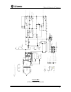
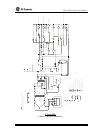
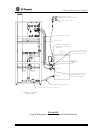
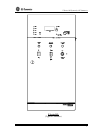
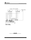
Z Series RO
(External RO Controller Wiring Connections)