


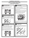
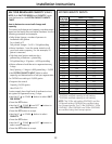
PLUMB “IN” AND “OUT” PIPES
TO AND FROM SOFTENER
CAUTION: Observe all of the following
cautions as you connect inlet and outlet
plumbing. See Typical Installation Illustration.
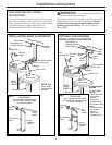
• BE SURE INCOMING HARD WATER SUPPLY IS
DIRECTED TO THE SOFTENER VALVE INLET PORT.
If house water flow is from the right, use a
plumbing crossover as shown in Typical
Installation Illustration.
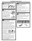
• With the softener in place, determine the
correct length of piping required to connect the
household plumbing to the 1″ copper adapter
on the softener. Test fit all connections.
NOTE: The softener must not support the home’s
plumbing in the vertical direction. Secure the
inlet and outlet pipes to the wall/ceiling using pipe
clamps or straps. Be certain the home’s plumbing
does not exert any force on the softener bypass.
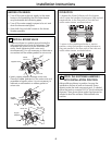
• Remove softener from installation space.
• Disconnect copper adapters and union nuts from
bypass valve.
• Reconnect copper adapters with union nuts
and gaskets in place to home plumbing. Before
soldering adapters, slide union nuts and gasket
away from area being soldered. NOTE: Torch heat
will damage plastic parts.
• Support inlet and outlet plumbing in some manner
(use pipe hangers or clamps) to keep the weight
off of the valve fittings.
• Slide softener back into position.
• Make final connections to the bypass valve.
3
Installation Instructions
7
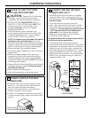
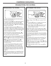
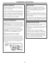
CONNECT AND RUN THE VALVE
DRAIN HOSE
• Check that drain port on valve body has white
tape on it. If not, apply Teflon Tape to threads
prior to installing the valve drain fitting.
• Connect valve drain fitting to valve drain port.
Tighten connection with a wrench.
• Connect 1/2″ diameter drain hose (not provided)
to the valve drain fitting. Tighten connections with
wrench.
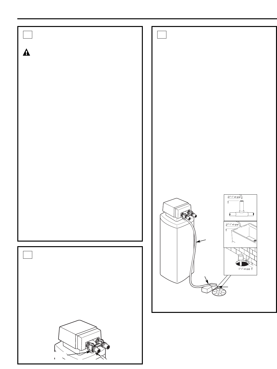
4
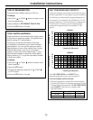
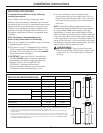
CONNECT AND RUN THE VALVE
DRAIN HOSE
(CONT.)
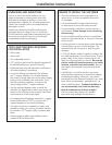
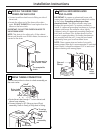
• Locate the other end of the hose at a suitable
drain point (floor drain, sump, laundry tub, etc.)
that terminates at the sewer. Check and comply
with local codes.
• Tie or wire the hose in place at the drain
point. High water pressure will cause it to whip
during the back-wash and fast rinse cycles of
regeneration. Also provide an air gap of at least
1-1/2″ between the end of the hose and the
drain point. An air gap prevents possible
siphoning of sewer water into the softener,
if the sewer should “back-up.”
The water softener will not work if water cannot
exit this hose during regeneration.
• Elevating the drain hose may cause back
pressure that could reduce the brine draw during
regeneration. If raising the drain line overhead is
required to get to the drain point, measure the
inlet water pressure to the softener first. For inlet
pressures between 20 and 50 psi, do not raise
higher than 8′ above the floor. For inlet pressure
above 50 psi, the drain line may be raised to a
maximum height of 14′.
4
Valve
drain
hose
FLOOR DRAIN
Tie or
wire hose
in place
1
1
⁄2″ air gap
LAUNDRY TUB
SUMP
STANDPIPE
Valve drain
hose connection