


1. Disconnect power to the control by unplugging the wall
transformer or unplugging the power cord from the bottom
of the control.
2. Press down on the top of the drive gear to disengage the
cam gear.
3. With the cam gear disengaged, rotate the cam gear
counterclockwise to the REFILL position until the air check
fills with water, and water flows through the brine line into
the brine tank. Do not run for more than three minutes.
4. Press down on the drive gear, and rotate the cam gear
counterclockwise to the DRAW/RINSE position. Check that
water is being drawn from the brine tank. The water level
in the brine tank will recede very slowly. Observe the water
level for at least one minute. If the water level does not
recede, if it goes up or if air enters the transparent air
check chamber and the ball falls and seats, refer to
the Troubleshooting section in this manual.
5. When water is being drawn from the brine tank,
press down on the drive gear and rotate the cam gear
counterclockwise to just before the SERVICE position.
Connect power to the control and allow the motor to drive
the cam gear to the SERVICE position. The motor will stop.
Run cold water from a nearby faucet until the water is
clear and soft.
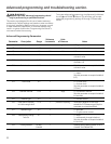
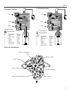
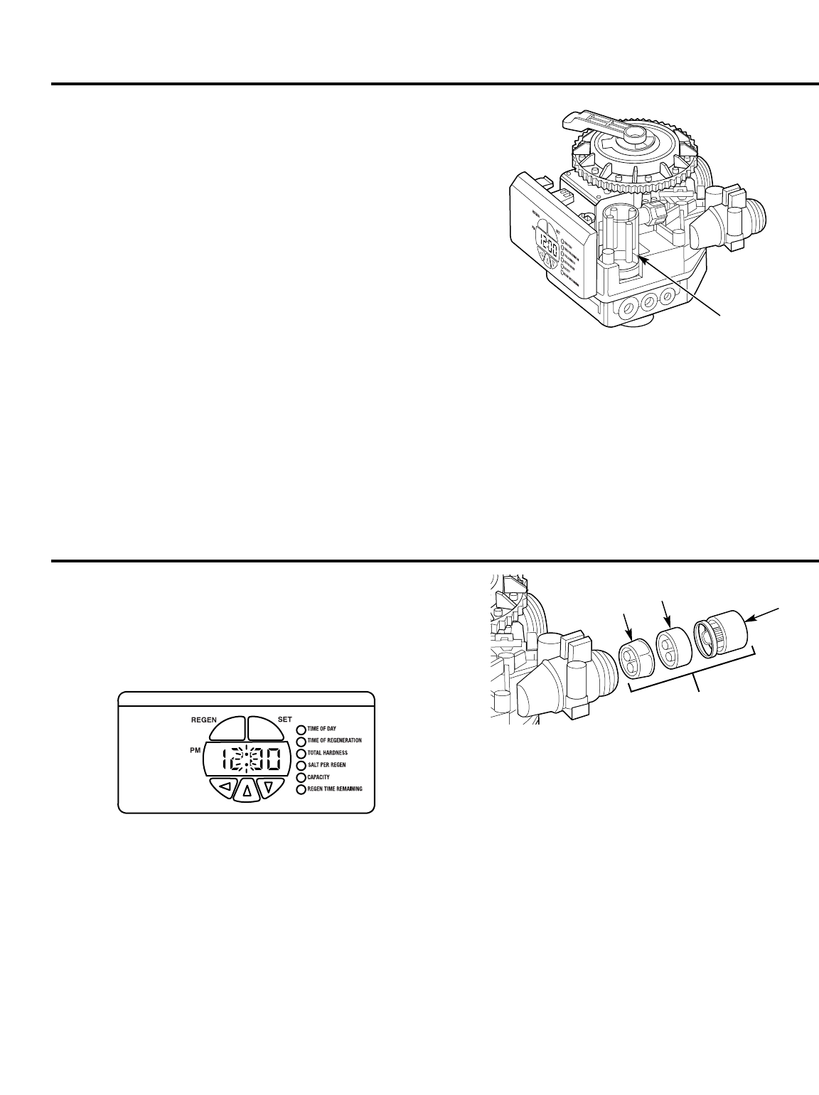
Checking the brine draw and refill function.
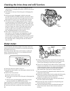
In rare instances, the turbine wheel of the water meter can
collect small particles of oxidized iron, eventually preventing
the wheel from turning.
If the flow indicator light does not blink when conditioned
water is flowing from the unit, it is an indication that the
turbine wheel is not turning.
1. Disconnect electrical power to the unit.
2. Shut off the water supply or put the bypass valve(s) into the
BYPASS position.
3. Relieve resin tank pressure:
A. Remove control valve cover.
B. Press down on the top of the drive gear to disengage the
cam gear.
C. With the cam gear disengaged, rotate the cam gear
counterclockwise to the BACKWASH position.
Check that there is no water flow through the drain line
before performing service or preventative maintenance.
4. Disconnect the water conditioner from the plumbing.
5. Using a needle-nose pliers, remove the outer gland and
the turbine wheel from the outlet of the valve. Generally,
it will not be necessary to remove the inner gland.
6. Clean all iron deposits and/or debris off the turbine wheel.
Excessive accumulation of iron may be removed from the
components with a solution of sodium hydrosulfite (or
sodium disulfite). Rinse the components thoroughly in
clean water after using the iron removal solution.
7. Flush accumulated iron deposits and/or debris from the
inside of the valve outlet.
8. Reinstall the turbine wheel into the outlet side of the valve,
being certain that the turbine wheel shaft is carefully
seated into the bearing of the inner gland.
9. Carefully reinstall the outer gland into the outlet side of
the valve. Check turbine rotation.
10. Reconnect the water conditioner to the plumbing and
follow Initial Start-Up section.
11. Open the downstream faucet (conditioned water) and
check to be certain that the flow indicator (colon) is
blinking.
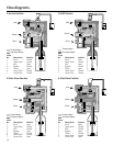
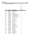
Water meter.
30
Air
check
Outer
gland
Turbine
wheel
Inner
gland
Turbine assembly