


5
Installation Instructions
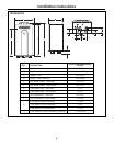
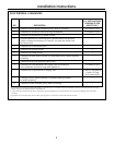
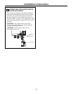
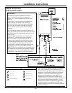
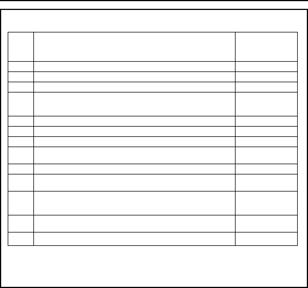
FLUE TERMINAL CLEARANCES
U.S. INSTALLATIONS
CLEARANCES PER
REF DESCRIPTION ANSI Z21.10.3
A Clearance above grade, veranda, porch, deck or snowline 36 inches (91 cm)
B Clearance to window or door that may be opened 12 inches (30 cm)
C Clearance to permanently closed window *
D Vertical clearance to ventilated soffit, located above the terminal *
within a horizontal distance of 2 feet (61 cm) from the center line
of the terminal
E Clearance to unventilated soffit *
F Clearance to outside corner *
G Clearance to inside corner *
H Clearance to each side of center line extended above meter/regulator *
assembly
I Clearance to service regulator vent outlet *
J Clearance to nonmechanical air supply inlet to building or 12 inches (30 cm)
the combustion air inlet to any other appliance
K Clearance to a mechanical air supply inlet 3 feet (91 cm) above
if within 10 feet
(3 m) horizontally
L Clearance above paved sidewalk or paved driveway located *
on public property
1
M Clearance under veranda, porch, deck or balcony
2
*
*For clearances not specified in ANSI Z223.1/NFPA 54, clearances are in accordance with local installation codes and the requirements of the gas
supplier. Clearance to opposite wall is 24 inches (60 cm).
1 A vent shall not terminate directly above a sidewalk or paved driveway that is located between two single family dwellings and serves both
dwellings.
2 Permitted only if veranda, porch, deck or balcony is fully open on a minimum of two sides beneath the floor.