


12
Installation Instructions
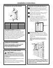
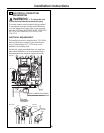
WATER PIPING
GENERAL INSTRUCTIONS
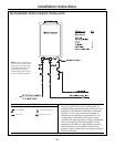
• The water supply should be shut off while
connecting the water heater. Make sure the
water inlet and outlet lines to the water heater fit
in the diagram shown on page 7. A manual water
control valve must be placed in the water inlet
connection to the water heater before it is
connected to the water line. Unions can be
used on both the hot and cold water lines for
future servicing and disconnection of the unit.
• The piping (including soldering materials) and
components connected to this appliance must
be approved for use in potable water systems.
• Purge the water line to remove all debris and air.
Debris will damage the water heater.
• Toxic chemicals such as those used for boiler
water treatment are not to be introduced to the
potable water used for space heating.
• If the appliance will be used as a potable water
source, it must not be connected to a system
that was previously used with a nonpotable
water heating appliance.
• Ensure that the water filter on the water heater
is clean and installed. See the Cleaning the inlet
filter section on page 19.
• New plumbing typically has contamination
in the lines. The inlet water filter should be
cleaned immediately after initial use.
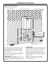
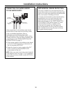
CAUTION: Hot Water outlet pipes leaving
unit can be hot to touch. Insulation must be used
for hot water pipes below 36″ due to burn risk to
children.
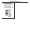
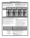
PRESSURE RELIEF VALVE
• Make sure the pressure relief valve is installed
so there is clearance if the optional pipe cover
(AGTPCM) is installed.
• An approved pressure relief valve is required
by the American National Standard (ANSI
Z21.10.3)/Canadian Standard (CSA 4.3)
for all water heating systems.
• The relief valve must comply with the standard
for Relief Valves and Automatic Gas Shutoff
Devices for Hot Water Supply Systems (ANSI
Z21.22) and/or the standard Temperature,
Pressure, Temperature and Pressure Relief
Valves and Vacuum Relief Valves, CAN1-4.4.
3
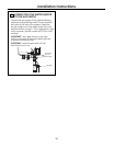
WATER PIPING (cont.)
PRESSURE RELIEF VALVE (cont.)
• The relief valve must be rated up to 150 psi and
to at least the maximum BTU/hr of the appliance.
• The discharge from the pressure relief valve
should be piped to the ground or into a drain
system to prevent exposure or possible burn
hazards to humans or other plant or animal life.
Follow local codes. Water discharged from the
relief valve could cause severe burns instantly,
scalds or death.
• The pressure relief valve must be manually
operated once a year to check for correct
operation.
• The relief valve should be added to the hot water
outlet line according to the manufacturer’s
instructions. DO NOT place any other type of
valve or shut-off device between the relief valve
and the water heater.
• Do not plug the relief valve and do not install any
reducing fittings or other restrictions in the relief
line. The relief line should allow for complete
drainage of the valve and the line.
• If a relief valve discharges periodically, this may
be due to thermal expansion in a closed water
supply system. Contact the water supplier or
local plumbing inspector on how to correct this
situation. Do not plug the relief valve.
• Neither GE nor the American National Standard
(ANSI Z21.10.3)/Canadian Standard (CSA 4.3)
requires a combination temperature and
pressure relief valve for this appliance; however,
local codes may require a combination
temperature and pressure relief valve.
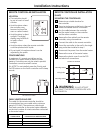
INTERNAL BUILT-IN FREEZE PROTECTION
• The freeze protection features include
electrical heating elements and intermittent firing
of the burner. Freeze protection may be disabled
if electricity or gas is not supplied, or if there is
an error preventing the water heater from
functioning.
NOTE: See Supplemental Freeze Protection
on page 13.
3
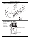
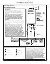
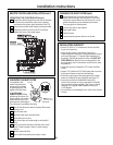
CONNECTING THE WATER HEATER TO GAS AND WATER (cont.)