


14
15
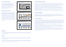
Superimposed ignitors
In many installations Ceramic Metal Halide lamps are
operated from a conventional magnetic ballast in
conjunction with a superimposed ignitor. These ignitors
generate starting pulses independently from the ballast and
should be placed close to the lamp, preferably within the
luminaire. Wiring between ignitor and lamp should have a
maximum capacitance to earth of 100pF (length equivalent
to less than 1 Metre) - contact ignitor manufacturer for details
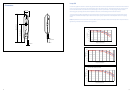
of specific ignitor types. A typical circuit diagram is shown:
Suitable Ignitors
Suitable high-energy (superimposed) ignitors recommended by control gear manufacturers are listed below. Check 0with
suppliers for their current range of ignitors. Lamp re-starting under warm lamp conditions can take up to 15 minutes. Suitable
ignitors to achieve a warm restart of less than 15 minutes include the following, however the list may not be fully inclusive:
Maker Products
APF
SP23
BAG Turgi
NI 150 SE NI 150 SE-TM20 MZN 150 SE-C NI 400 LE/3.5 A NI 400 LE/3.5 A-TM20
ERC
AZ A 1.8 AZ P 1.8 AZ P 1.8 T3 AZ P 1.8 T3 AZ P 3.0 T3
Helvar
L-150 LSI-150T20
Magnetek/May & Christe
ZG 0.5 ZG 2.0 ZG 2.0D ZG 4.5D
Parry/Parmer
PAV400 PCX400 PXE100
Philips
SU20S
Thorn
G53459 G53498 G53476 G53504.TB
Tridonic
ZRM 1.8-ES/B ZRM 2.5-ES/B ZRM 4.5-ES/B ZRM 6-ES/B ZRM 2.5-ES/B
Vossloh-Schwabe
Z 150 Z 150 K Z 150 K A10 Z 150 K A10 Z 250
Neutral
Phase
Ballast
PFC Capacitor
Ignitor
B
Lp
N
Typical superimposed ignitor circuit
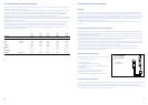
Impulser ignitors
Impulser type ignitors use the ballast winding as a pulse
transformer and can only be used with a matched ballast.
Always check with the ballast and ignitor supplier that
components are compatible. Longer cable lengths between
ballast & ignitor and the lamp are possible due to the lower
pulse frequency generated, giving greater flexibility for
remote control gear applications. Ignitor pulse characteristics
at the lamp must however comply with specified minimum
values for ConstantColor CMH™ lamps under all conditions.
Other ignitor related considerations
Timed or Cut-out Ignitors
The use of a ‘timed’ or ‘cut-out’ ignitor is not a specific requirement for ConstantColor CMH™ lamps but it is a good optional
safety feature worth considering to prolong ignitor component life. The timed on-period must be adequate to allow lamps to
cool and restart as described below. A period of 10-15 minutes continuous or intermittent operation is recommended before
the ignitor automatically switches off. Timed ignitors specifically offered for High-Pressure Sodium lamps where the period of
operation is less than 5 minutes are not suitable for ConstantColor CMH™ lamps.
Hot Re-strike
All ratings re-strike within 15 minutes following a short interruption in the supply. Actual re-strike time is determined by the
ignitor type, pulse voltage and cooling rate of the lamp. Instant hot re-strike is only possible using a suitable very high voltage
ignitor and a double ended lamp. GE Lighting should be consulted when considering use of an instant hot re-striking system.
Warm Re-starting
The combined characteristics of ceramic arc-tube material and vacuum outer jacket result in ConstantColor CMH™ lamps
cooling relatively slowly. It is possible with low energy ignitors to reach the required breakdown voltage but not create a full
thermionic discharge. Under these conditions the lamp can remain very warm and be prevented from cooling to a temperature
at which the arc can be re-established. To avoid this, turn off the power supply for approximately fifteen minutes or change to
a suitable high energy ignitor from the list given in the superimposed ignitor section.
Neutral
Phase
Ballast
PFC Capacitor
Ignitor
Typical impulser ignitor circuit
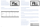
Fusing Recommendations
For a very short period immediately after switch-on, all
discharge lamps can act as a partial rectifier and a
conventional magnetic ballast may allow higher than the
normal current to flow. At switch-on the short duration
surge current drawn by the power factor correction capacitor
can be high. In order to prevent nuisance fuse
failure at initial switch-on, the fuse rating must take these
transient conditions into account. A separate technical
data sheet providing additional explanation and
information for the fusing of High Intensity Discharge
lighting circuits is available from GE Lighting.
Fusing of individual fixtures is recommended, in order to
provide added protection for end-of-life conditions when
lamp rectification can also occur.
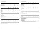
Number of Lamps
1
2 3 4 5 6
35W Fuse Rating (A)
4 4 4 4 4 4
70W Fuse Rating (A)
4 4 4 4 4 4
150W Fuse Rating (A)
4
4 4
6 6 10