


10
11
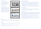
UV and damage to sensitive materials
The wall of the bulb, which is produced with specially developed ‘UV Control’ material, absorbs potentially harmful high energy
UV radiation emitted by the ceramic arc-tube.
The use of UV control material together with an optically neutral front glass cover allows the lamp to signicantly reduce the
risk of discolouration or fading of products. When illuminating light-sensitive materials or at high light levels, additional UV
ltration is recommended. Luminaires should not be used if the front glass is broken or missing. It is recommended that a
safety interlock switch is incorporated into the luminaire to prevent operation when the luminaire is opened.
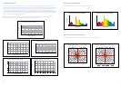
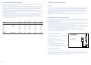
Although PET determines limits of human exposure to lamp UV, the risk of fading of mechanise due to UV can be quantied by
a Damage Factor and a Risk of Fading. The risk of fading is simply the numerical product of the illuminance, exposure time and
damage factor due to the light source.
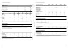
Finally the selection of luminaire materials should take into consideration the UV emission. Current UV reduction types on the
market are optimised for UV safety of human eye and skin exposure. However, luminaire materials may have different
wavelength dependent response functions. Designers must take account of emission in each of the UV-A, UV-B and UV-C
spectral ranges as well as material temperatures when designing luminaires. Typical values for UV-A, UV-B and UV-C range
radiation can be found in the table below.
Lamp type
20W
3000K
35W
3000K
35W
4200K
70W
3000K
70W
4200K
UV-PET Performance µW / (cm²) / 500LUX
UV C
220-280nm 0.036 0.0367 0.020 0.014 0.011
UV B
280-315nm 0.049 0.0467 0.040 0.006 0.009
UV A
315-400nm 10.170 10.360 113.870 6.980 9.800
UVC/UVB
10.720 0.786 0.509 2.365 1.321
UVB/UVA
0.005 0.005 0.003 0.001 0.0099
Eeff
0.052 0.034 0.015 0.014
PET (h)±10%
16 15 26 54 64
Risk Group
IESNA RP-27.3-96 Exempt Exempt Exempt Exempt Exempt
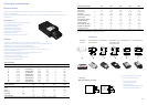
Information on luminaire design
Ballasts
ConstantColor CMH™ operate from the same type of ballast as conventional quartz technology metal halide lamps of the
same nominal power. IEC 61167 MH lamp standard and IEC62035 HID lamp safety standard specify use of ballast thermal
protection or equivalent protection device in the circuit. This safety device will protect the ballast and fixture from overheating
damage at lamp end-of-life should rectication occur due to electrode imbalance or arc-tube failure. The IEC61167
requirement applies to both ceramic and quartz arc tube metal halide lamps of the UV-A, UV-B and UV-C spectral ranges as
well as material temperatures when designing luminaires.
ConstantColor
TM
CMH G8.5 lamps are compatible with a list of approved ballasts; contact your GE representative for more
information.
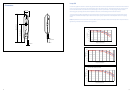
Stay magnetic field from conventional ballast
At the design stage for fixtures incorporating the control gear, careful consideration should be given to the physical layout of
the lamp and ballast. The relative positions and distance between lamp and ballast can adversely affect lamp performance
and drastically reduce lamp life survival.
Conventional magnetic ballasts can produce a stray magnetic field and if the lamp is placed within this field, “bowing” of the
arc in the discharge tube can occur. Since ceramic is a very rigid material severe arc bowing can cause high thermal stress
leading to cracking or rupture of the arc-tube resulting in failure of the lamp early in life.
Such bowing of the arc can also affect the quartz arc-tube in conventional metal halide lamps, but cracking or rupture failure
is less likely since quartz softens at the resulting higher wall temperature causing the arc-tube to become swollen. Excessive
swelling of a quartz arc-tube can however also result in cracking or rupture failure.
In fixtures where the ballast is necessarily placed close to the lamp, use of magnetic shielding is essential. Another
solution is to use an electronic ballast, which eliminates the need for an ignitor, simplies wiring, reduces the risk of
stray magnetic eld and eliminates light output icker.
Electronic ballast operation
CMH 20W is designed only for operation from electronic gear*.
This provides many advantages:
• Flicker free light output
• Well controlled electronic ignition process
• Simple wiring for xtures due to elimination of ignitor and
PFC capacitor
• Reduces xture weight
• Automatic sensing of failed lamps and shutdown
• Lower overall system power consumption
• On further details of operating gear please refer to GE
Containment requirement
ConstantColor CMH™ lamps operate above atmospheric pressure, therefore a very small risk exists that the lamp may shatter
when the end-of-life is reached. Although this failure mode is unlikely, containment of shattered particles is required as
prescribed by IEC 61167. ConstantColor CMH™ lamps should only be operated in a suitable enclosed luminaire with front cover
glass capable of containing the fragments of a lamp, should it shatter.
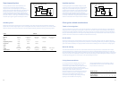
LH = Lamp holder
E = Electronic Gear
Circuit diagram
electronic ballast
N P
Mains
LH
E