


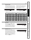
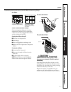
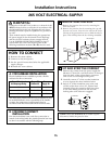
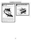
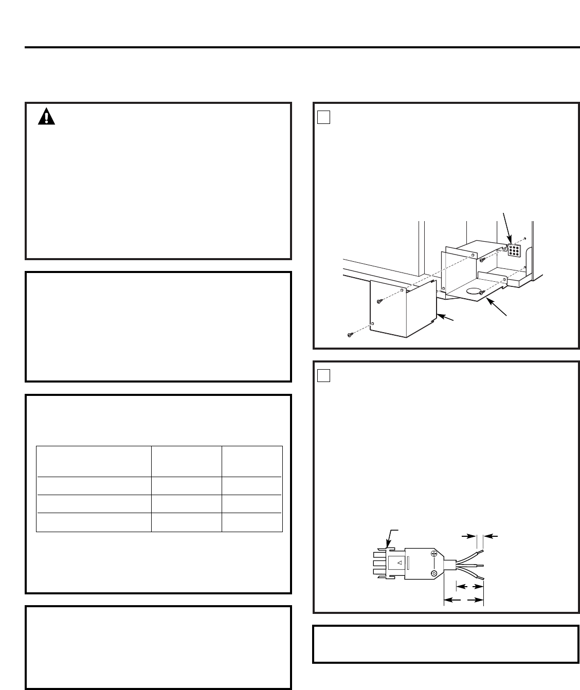
REMOVE JUNCTION BOX
1 Remove the junction box cover by removing the
front two screws.
2 Remove the junction box by removing the top and
bottom rear screws. Note how the tabs on the lower
left side of the junction box serve to hold the side in
place. This will help when the box is being reinstalled.
1
Unit connector
Junction
box cover
Junction
box
15
Installation Instructions
265 VOLT ELECTRICAL SUPPLY
WARNING:
Connection of this 265 V AC product to a branch circuit
MUST be done by direct connection in accordance with
the National Electrical Code. Plugging this unit into a
building mounted exposed receptacle is not permitted
by code.
These models must be installed using the appropriate
GE power supply kit for the branch circuit amperage
and the electrical resistance heater wattage desired.
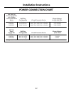
Use the POWER CONNECTION CHART on page 17
to determine the correct kit required. One of the
following installation methods (A or B) must be used.
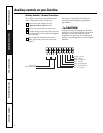
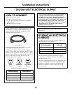
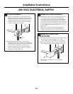
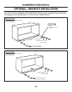
CUT AND STRIP THE CORDSET
1 Remove the cordset from the power supply kit.
Measure 6″ down the cord from where it emerges
from the back of the nylon plastic connector
and cut the cord through at this point.
2 Carefully remove 3″ of the cordset insulation
so as to expose the three insulated wires.
3 Strip 3/4″ of the insulation away at the end
of each of the three wires (L1, Neutral and
Ground). Plug the connector fully into place
in the unit mating connector. Be sure the
locking tabs at the sides are engaged.
2
3/4″
3″
Connector
6″
NOTE: Order Kit RAK4002CW to enable a quick
disconnect inside the junction box.
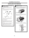
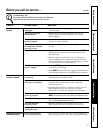
A. FOR SUBBASE INSTALLATION
Electrical subbase kits are available to provide a flexible
enclosure for direct connection.
The instructions provided with the selected subbase kit must
be carefully followed. It is the responsibility of the installer
to ensure the connection of components is done in
accordance with these instructions and all electrical codes.
Branch Circuit and Proper GE Power
Unit Amperage Rating Subbase Kit Supply Kit
15 RAK204E15 RAK5172
20 RAK204E20 RAK5202
30 RAK204E30 RAK5302
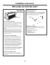
B. FOR DIRECT CONNECT
INSTALLATION
If an electrical subbase is not used, direct connection to
branch circuit wiring inside the provided junction box must
be done in accordance with the following steps.
HOW TO CONNECT
1 Remove the room cabinet.
2 Connect to electrical power.
3 See the special instructions below for applicable
supply voltages.
4 Reinstall the room cabinet.